64 FLOWSIC600-XT · Operating Instructions · 8018846/1BHP/V2-1/2021-05 · © SICK Engineering GmbH
Installation
Subject to change without notice
3.4.3 Criteria for electrical connection
Installation work → p. 42, §3.3 must be completed.
3.4.4 Electrical connections
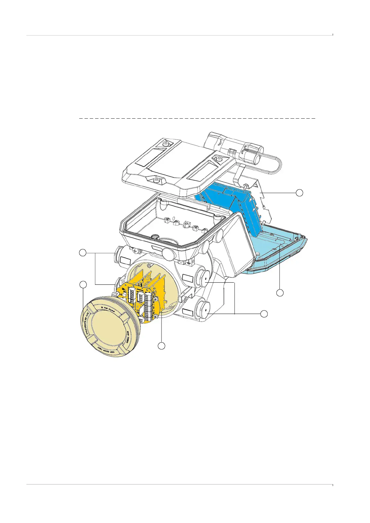
The Signal Processing Unit enclosure of the FLOWSIC600-XT comprises a flameproof enclo-
sure and an adjacent separate chamber. With Ex-e wiring (→ Fig. 30), the Ex-d inputs and
outputs run through a line duct to the Ex-e terminals in the Ex-e terminal compartment.
Fig. 29 Ex-d enclosure version
1
2
4
5
1 Flameproof enclosure with I/O electronics
2 Ex-d terminal compartment cover
3 Cable gland (4 xM25 or 3/4“ NPT), with flameproof sealing plug;
cable ducts must be ordered separately or provided by the customer
4 Ex-i transducer electronics with cover and backup battery
5 Display unit
3
3