Installation
FLOWSIC600-XT · Operating Instructions · 8018846/1BHP/V2-1/2021-05 · © SICK Engineering GmbH 45
Subject to change without notice
3.3.4.1 Installation configurations
Unidirectional
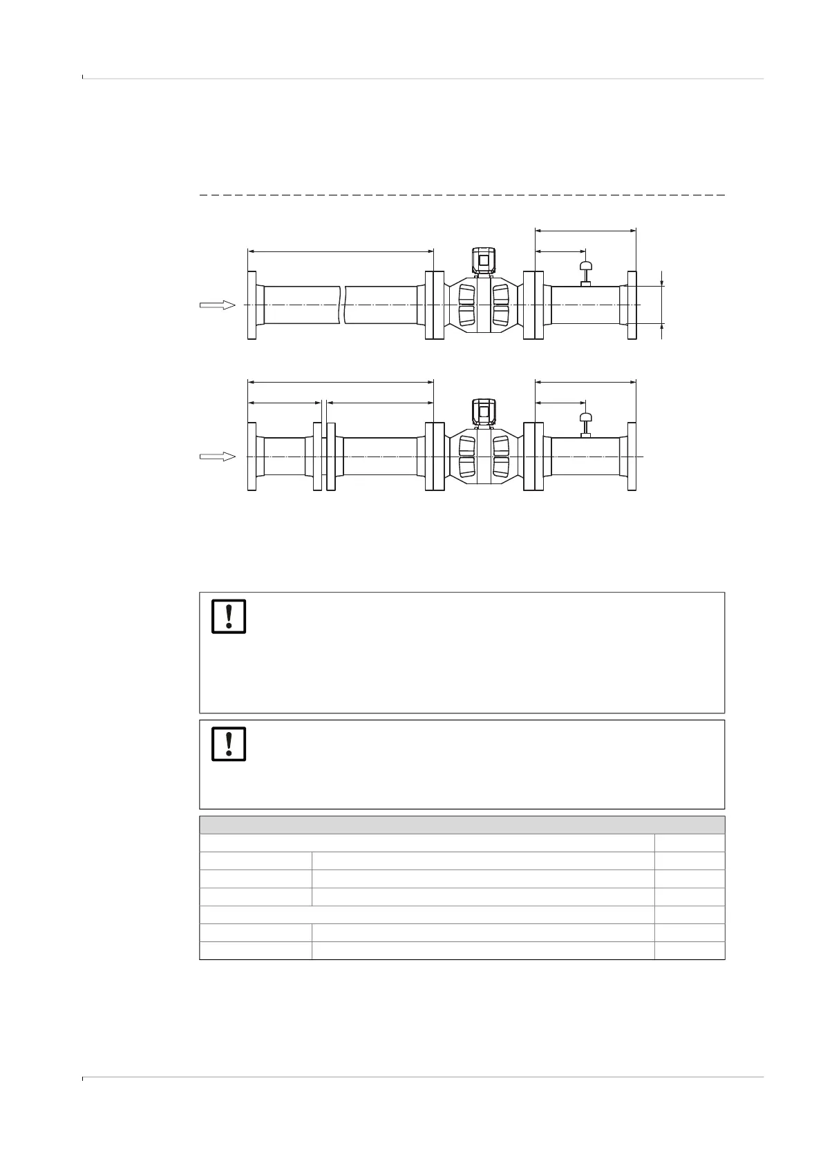
Fitting the FLOWSIC600-XT for unidirectional flow.
Fig. 19 Unidirectional use
[1]
Characterized by CPA or SICK flow conditioners.
[2]
Better repeatability and linearity is achieved by using a flow conditioner;
but both configurations meet the performance requirements of AGA 9.
NOTICE:
Installation configuration (B) with the flow conditioner refers exclusively to
SICK conditioner types (according to SICK documents 9211778 and
9211779). When using conditioner types CPA 50E or 55E, a distance between
the conditioner and meter of at least 10DN inlet length must be considered.
When other conditioners are used, the installation configuration can be differ-
ent and must be agreed with SICK.
NOTICE:
During operation, it is imperative to use the same flow conditioner as well as
the same pipes, in the same orientation as when calibrating the meter. Mark
the pipes and flow conditioner to indicate the flange alignment at the time of
calibration.
Configuration 1 (A)
OIML R137 A
4 measuring paths Class 1.0 10 DN
8 measuring paths Class 1.0 2 DN
8 measuring paths Class 0.5 5 DN
AGA Report 9 3rd Edition, July 2017 A
4 measuring paths Metering package performance per §6.3
1
20 DN
8 measuring paths Metering package performance per §6.3
1,2
5 DN
≥ A
E
DN
≥ A
D
D
E
≥ C≥ B
1
1
2
2
3
A
B
1. FLOWSIC600-XT
2. Temperature measuring point
3. SICK flow conditioner