Commissioning and Operation
FLOWSIC600-XT · Operating Instructions · 8018846/1BHP/V2-1/2021-05 · © SICK Engineering GmbH 91
Subject to change without notice
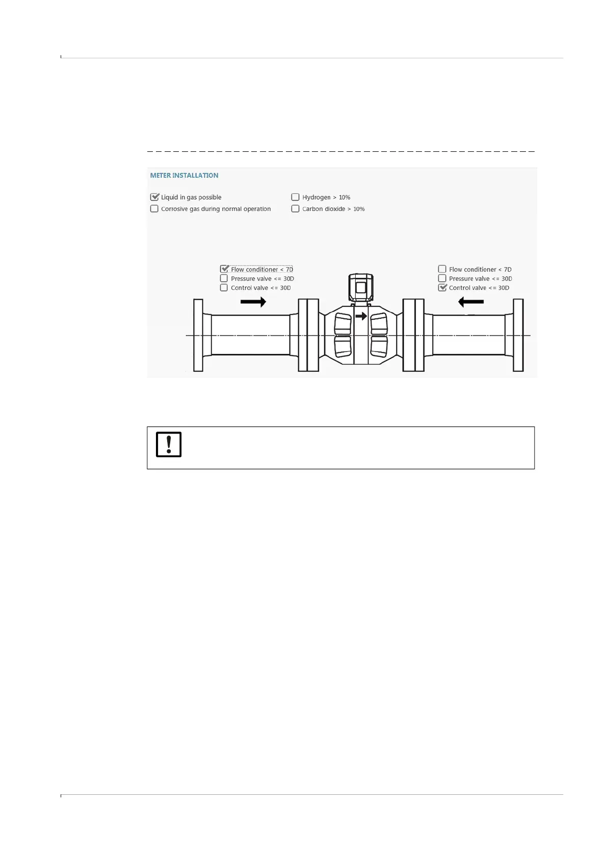
4.3.2.8 Meter installation
Specifications on the installation conditions of the gas flow meter are relevant for trouble-
shooting with i-diagnostics
TM
.
The arrow symbol on the gas flow meter shown identifies the primary flow direction.
Fig. 43 Installation conditions (example)
4.3.2.9
Completion
▸
First write the data to the device.
▸
If desired; Reset the malfunction volume encoder totalizer and clear the logbooks.
▸
SICK recommends creating a Parameter report and a Maintenance report and archiving
the reports with the delivery documentation, → p. 101, §5.2.4.
4.4 Function check after commissioning
4.4.1 Recommended checks:
▸
Checking the meter state, → p. 96, §5.2.1.
▸
Checking the signal acceptance rate, → p. 92, §4.4.2.
▸
Zero phase check, → p. 92, §4.4.3.
▸
Checking the speed of sound, → p. 93, §4.4.4.
▸
Comparing theoretical and measured sound velocity (SOS), → p. 98, §5.2.2.
NOTICE:
The data must be written to the device before the report is created otherwise
the reports are created using the data from commissioning.