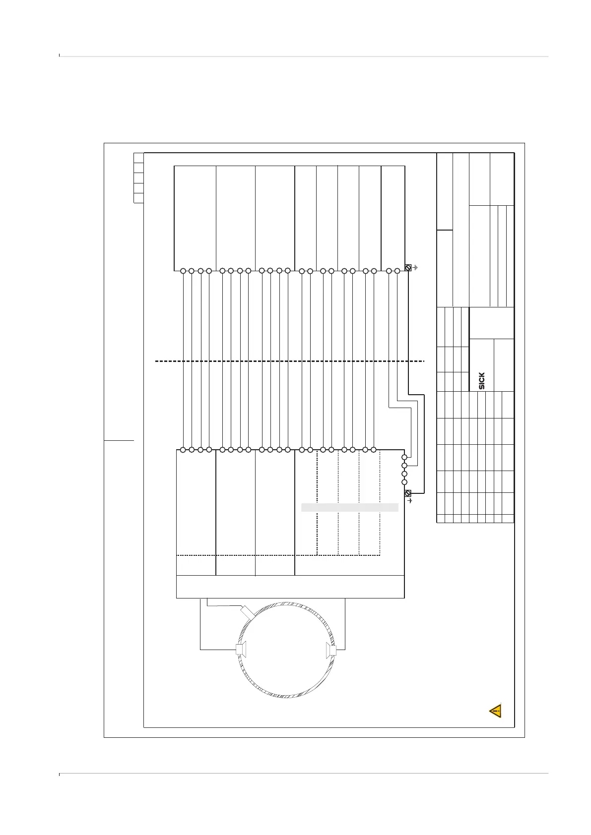
Fig. 72 Connection diagram 9236581 (page 1)
Vervielfaeltigung dieser Unterlage sowie Verwertung und Mitteilung ihres
Inhaltes unzulaessig, soweit nicht ausdruecklich zugestanden. Zuwiderhand-
lungen sind strafbar und verpflichten zu Schadenersatz (LitUrhG, UWG, BGB).
Alle Rechte fuer den Fall der Patenterteilung oder GM-Eintragung vorbehalten.
A4_Formblatt_ME10.CDR
SICK Engineering GmbH
Bergener Ring 27
01458 Ottendorf-Okrilla
Verteildatum:
Page
Norm-Typ/DIN
Ersatz für:
Änderung
gepr.
gez.
Tag Name
Ind. Tag Name
Maßstab:
Werkstoff
Ersetzt durch:
Gepr.
Ursprung:
1of15
Safety parameters of interconnected equipments must be complied
as follows: Uo < Ui, Io < Ii, Po< Pi, Co > Ci + Ccable, Lo > Li + Lcable
Hazardous (classified) location
Safe Area
Control Drawing FLOWSIC600-XT CSA
9236581
Associated Equipment
Uo <= 20 V,
Po <= 717 mW
Uo <= 20 V,
Po <= 717 mW
Uo <= 20 V,
Po <= 717 mW
Uo <= 20 V,
Po <= 717 mW
Uo <= 10.5 V
Po <= 717 mW
Co >= 1.21 μF + C
Lo >= 0.02 mH + L
cable
cable
Uo <= 10.5 V
Po <= 717 mW
Co >= 1.21 μF + C
Lo >= 0.02 mH + L
cable
cable
Uo <= 10.5 V
Po <= 717 mW
Co >= 1.21 μF + C
Lo >= 0.02 mH + L
cable
cable
+-
+-
+-+-+-
WARNING:
AVERTISSEMENT:
EXPLOSION HAZARD
Substitution of components may impair Intrinsic safety
RISQUE D` EXPLOSION - La substitution
de composants peut compromettre la securite intrinseque.
Class I Division 1, Groups A, B, C, D, T4
Ex ia Intrinsically Safe; Securite Intrinseque
Ex ia IIC T4 Ga
Class I Zone 1 AEx ia op is IIC T4 Ga
-40°C < Tamb < 70°C
AB+-
AB+-
AB+-
Ui = 10.5 V
Pi = 717 mW
Ci = 1.21 μF
Li = 0.02 mH
RS485
optical isolated
needs ext. power
AB+-
Ui = 10.5 V
Pi = 717 mW
Ci = 1.21 μF
Li = 0.02 mH
RS485
optical isolated
needs ext. power
AB+-
Ui = 10.5 V
Pi = 717 mW
Ci = 1.21 μF
Li = 0.02 mH
RS485
optical isolated
needs ext. power
AB+-
Ui=20V
Pi = 717 mW
Ui=20V
Pi = 717 mW
Ui=20V
Pi = 717 mW
Ui=20V
Pi = 717 mW
+-
+-+-+-
DO.3
optical isolated
DO.2
optical isolated
FO.1
optical isolated
FO.0
optical isolated
DO-LF
Module slot
UAR
T3
Module slot
UART2
Module slot
UART0
Module slot
Digital outputs with Power input
SPU
I/O configuration with modules “DO-LF”+3x“RS485”
Temperature range
and pressure range
see Marking plate
internal SPI
pressure sensor
not available for
Tgas >105°C
FLOWSIC600-XT
(F6*-******-*I1A-****)
Up to 16 ultrasonic transducers,
only manufactured by SICK
ext. Power
6...16 Vdc
-+-+
In the US install in accordance with the NEC (NFPA70, Article 504)
and ANSI/ISA-RP12.06.01
In Canada install in accordance with CEC part 1.
Read operation instructions before installation.
kochami
kochami
2015-10-30
2016-01-27
Ui=20V
Ii = 667 mA
Pi = 1.65 W
Li = 0.005 mH
Uo <= 20 V
Io <= 667 mA
Po <= 1.65 W
Lo >= 0.005 + Lcable
01
ZAK3
kochami
kochami
2017-03-29
2017-03-29