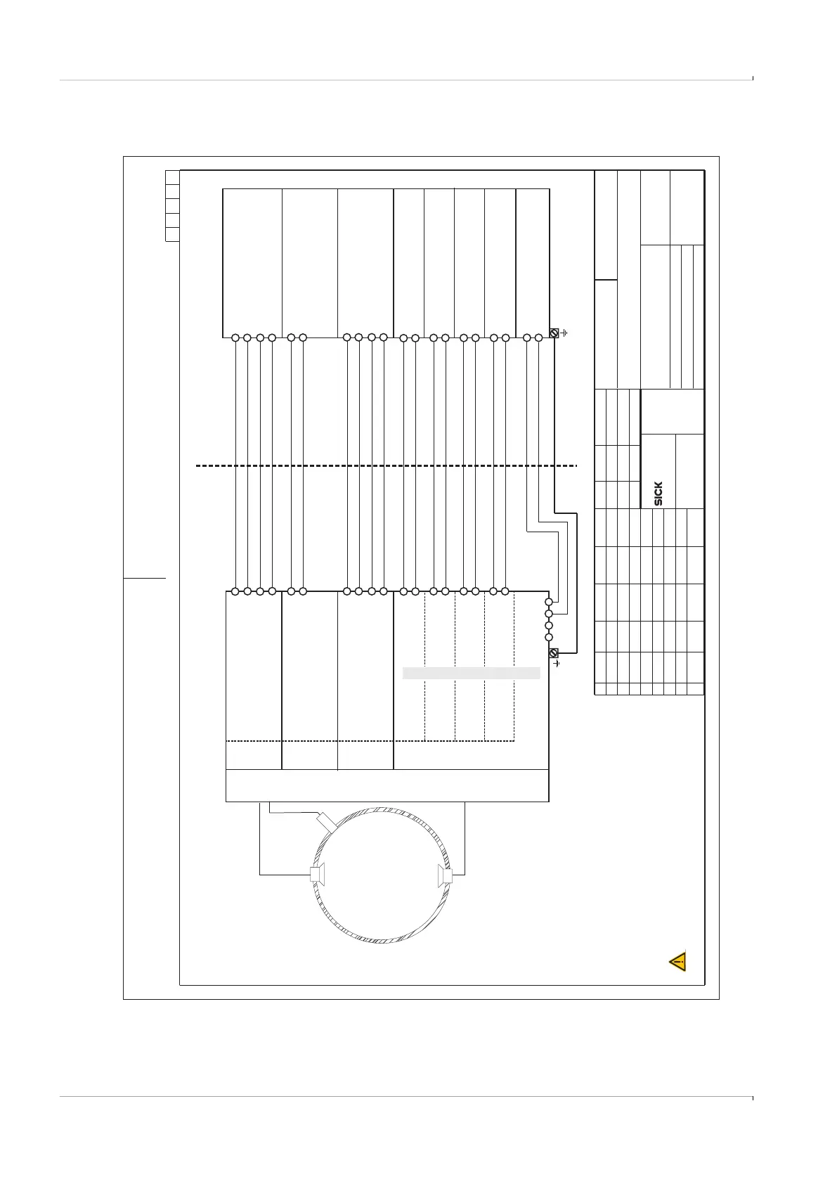
Fig. 73 Connection diagram 9236581 (page 5)
Vervielfaeltigung dieser Unterlage sowie Verwertung und Mitteilung ihres
Inhaltes unzulaessig, soweit nicht ausdruecklich zugestanden. Zuwiderhand-
lungen sind strafbar und verpflichten zu Schadenersatz (LitUrhG, UWG, BGB).
Alle Rechte fuer den Fall der Patenterteilung oder GM-Eintragung vorbehalten.
A4_Formblatt_ME10.CDR
SICK Engineering GmbH
Bergener Ring 27
01458 Ottendorf-Okrilla
Verteildatum:
Page
Norm-Typ/DIN
Ersatz für:
Änderung
gepr.
gez.
Tag Name
Tag Name
Maßstab:
Werkstoff
Ersetzt durch:
Gepr.
Ursprung:
5of15
Safety parameters of interconnected equipments must be complied
as follows: Uo < Ui, Io < Ii, Po< Pi, Co > Ci + Ccable, Lo > Li + Lcable
Hazardous (classified) location
Safe Area
9236581
Associated Equipment
Uo <= 20 V,
Po <= 717 mW
Uo <= 20 V,
Po <= 717 mW
Uo <= 20 V,
Po <= 717 mW
Uo <= 20 V,
Po <= 717 mW
Uo <= 10.5 V
Po <= 717 mW
Co >= 1.21 μF + C
Lo >= 0.02 mH + L
cable
cable
Uo <= 18.2 V
Po <= 1 W
Uo <= 10.5 V
Po <= 717 mW
Co >= 1.21 μF + C
Lo >= 0.02 mH + L
cable
cable
+-
+-
+-+-+-
SPU
I/O configuration with modules “DO-LF”+2x“RS485” + “ENCODER”
AB+-
+-
AB+-
Ui = 10.5 V
Pi = 717 mW
Ci = 1.21 μF
Li = 0.02 mH
RS485
optical isolated
needs ext. power
AB+-
Ui = 18.2 V
Pi=1W
ENCODER
optical isolated
+-
Ui = 10.5 V
Pi = 717 mW
Ci = 1.21 μF
Li = 0.02 mH
RS485
optical isolated
needs ext. power
AB+-
Ui=20V
Pi = 717 mW
Ui=20V
Pi = 717 mW
Ui=20V
Pi = 717 mW
Ui=20V
Pi = 717 mW
+-
+-+-+-
DO.3
optical isolated
DO.2
optical isolated
FO.1
optical isolated
FO.0
optical isolated
DO-LF
Module slot
UAR
T3
Module slot
UART2
Module slot
UART0
Module slot
Digital outputs with Power input
Temperature range
and pressure range
see Marking plate
internal SPI
pressure sensor
not available for
Tgas >105°C
Up to 16 ultrasonic transducers,
only manufactured by SICK
ext. Power
6...16 Vdc
-+-+
kochami
kochami
2015-10-30
Control Drawing FLOWSIC600-XT CSA
Ind.
2016-01-27
WARNING:
AVERTISSEMENT:
EXPLOSION HAZARD
Substitution of components may impair Intrinsic safety
RISQUE D` EXPLOSION - La substitution
de composants peut compromettre la securite intrinseque.
Class I Division 1, Groups A, B, C, D, T4
Ex ia Intrinsically Safe; Securite Intrinseque
Ex ia IIC T4 Ga
Class I Zone 1 AEx ia op is IIC T4 Ga
-40°C < Tamb < 70°C
In the US install in accordance with the NEC (NFPA70, Article 504)
and ANSI/ISA-RP12.06.01
In Canada install in accordance with CEC part 1.
Read operation instructions before installation.
FLOWSIC600-XT
(F6*-******-*I1J-****)
Ui=20V
Ii = 667 mA
Pi = 1.65 W
Li = 0.005 mH
Uo <= 20 V
Io <= 667 mA
Po <= 1.65 W
Lo >= 0.005 + Lcable
01
ZAK3
kochami
kochami
2017-03-29
2017-03-29