Installation
FLOWSIC600-XT · Operating Instructions · 8018846/1BHP/V2-1/2021-05 · © SICK Engineering GmbH 63
Subject to change without notice
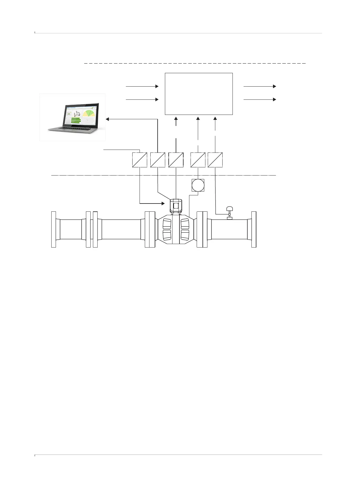
3.4.2 General connection of the FLOWSIC600-XT
Fig. 28 Connection diagram FLOWSIC600-XT
Safe area
Ex zone
classified Zone 1 or Zone 2
Service PC / higher-
level control system
RS485 / MODBUS
Volumetric
flow a. c.
Electronic Volume Corrector
(EVC) / Flow Computer (FC)
FLOWSIC600-XT
Compressibility factor Z
Heating value H
s
Gas volume flow rate
(std.)
Energy content
12 ... 24 V DC
(Ex i isolating transformer only
required for intrinsically safe
installation)
Pressure
Ex i Ex i Ex i Ex i Ex i
p
T
Temperature
6...16 V DC