82 FLOWSIC600-XT · Operating Instructions · 8018846/1BHP/V2-1/2021-05 · © SICK Engineering GmbH
Commissioning and Operation
Subject to change without notice
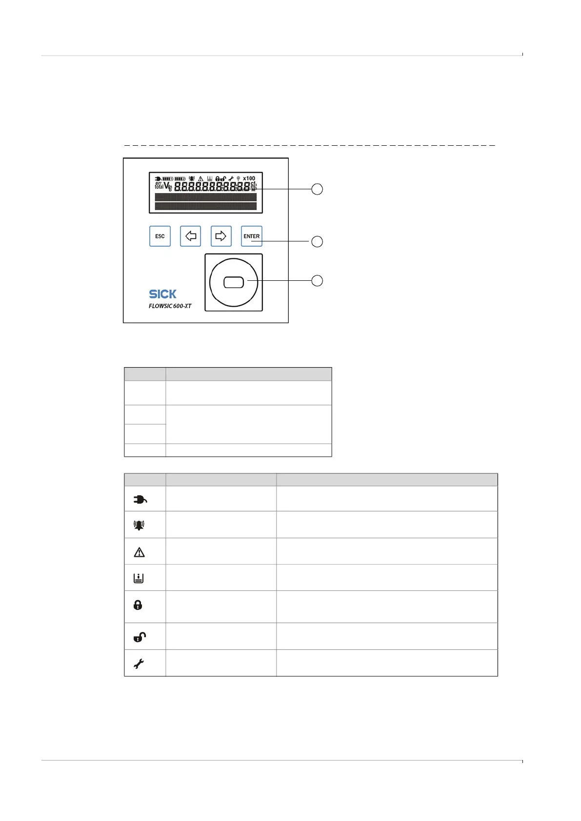
4.2.2 Display and operating elements
The FLOWSIC600-XT display comprises an LCD display for measuring screens and
configuring, 4 buttons for menu navigation and the possibility to attach an infrared/USB
adapter (Part No. 6050602) for data communication.
Fig. 37 Display and operating elements
4.2.3
Display in the symbol bar
1
3
2
1 Display
2 Buttons
3 Optical data interface (infrared)
Table 8 Buttons
In menu
Esc
Returns to next higher level of the
operator menu.
Toggles between single menu entries
on one level.
ENTER Calls up a submenu.
Table 9 Symbols
Symbol Significance Description
External power supply Always shown, blinks for faults in the external power supply.
Device status: Malfunction The device has an error, the measured value is invalid.
Device status: Warning The device has a warning, the measured value is still valid.
Registered events Events have occurred since the last event summary reset.
Parameter locking switch
closed
Metrologically relevant parameters are protected against
changing; modifications are registered in the Metrology
logbook.
Parameter locking switch
open
Metrologically relevant parameters can be changed; the
modifications are not saved in the Metrology logbook.
Configuration mode Configuration mode is active, parameters can be changed on
the device.