16 FLOWSIC600-XT · Operating Instructions · 8018846/1BHP/V2-1/2021-05 · © SICK Engineering GmbH
Product description
Subject to change without notice
2.1 Measuring principle
The FLOWSIC600-XT measuring system works according to the principle of ultrasonic tran-
sit time difference measurement. This allows conclusions to be made on the gas volume
flowing through based on the sound velocity transfer time. Measurement is carried out in a
direct path layout to keep disturbing effects such as gas flow turbulence, dirt, moisture or
interfering noises as low as possible. Two ultrasonic transducers are positioned opposite
each other in a defined angle to the gas flow and operate alternately as sender and
receiver.
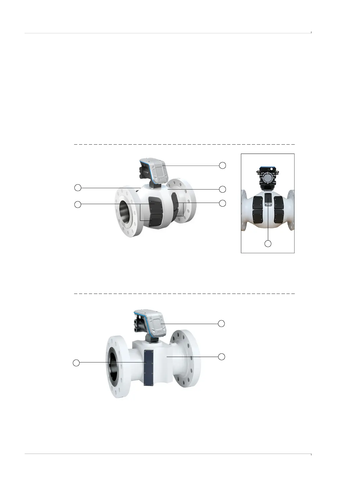
2.2 System components
The FLOWSIC600-XT measuring system consists of the following hardware components:
Fig. 2 Overview FLOWSIC600-XT
Fig. 3 Overview FLOWSIC600-XT C
1
2
3
3
4
1 Signal Processing Unit
2 Meter body
3 Cover caps for ultrasonic transducers
4 Cover cap for integrated pressure and temperature sensor
Rear view
4
1 Signal Processing Unit
2 Meter body
3 Cover cap for ultrasonic transducers
3
1
2