46 FLOWSIC600-XT · Operating Instructions · 8018846/1BHP/V2-1/2021-05 · © SICK Engineering GmbH
Installation
Subject to change without notice
[1]
Characterized by CPA or SICK flow conditioners.
[2]
Better repeatability and linearity is achieved by using a flow conditioner,
but both configurations meet the performance requirements of AGA 9.
Configuration 2 (B)
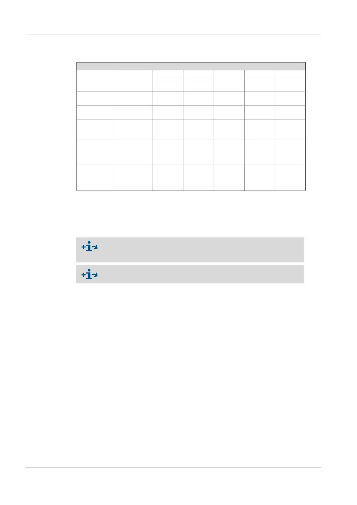
OIML R137 A B C D E
4 measuring
paths
Class 1.0 5 DN 2 DN 3 DN 3 DN 1-5 DN
4 measuring
paths
Class 0.5 10 DN 2 DN 8 DN 3 DN 1-5 DN
8 measuring
paths
Class 1.0/0.5 5 DN 2 DN 3 DN 3 DN 1-5 DN
AGA Report 9
3rd Edition,
July 2017
A B C D E
4 measuring
paths
Metering pack-
age perfor-
mance per
§6.3
1,2
10 DN 5 DN 5 DN 5 DN 2.5 DN
8 measuring
paths
Metering pack-
age perfor-
mance per
§6.3
1,2
5 DN 2 DN 3 DN 5 DN 2.5 DN
Local requirements for the inlet section may vary.
Installation requirements in accordance with GOST, see document “8020847
Installation Requirements GOST”
The maximum gas velocity in the pipe is limited to 40 m/s in configurations
with flow conditioner.