Installation
FLOWSIC600-XT · Operating Instructions · 8018846/1BHP/V2-1/2021-05 · © SICK Engineering GmbH 53
Subject to change without notice
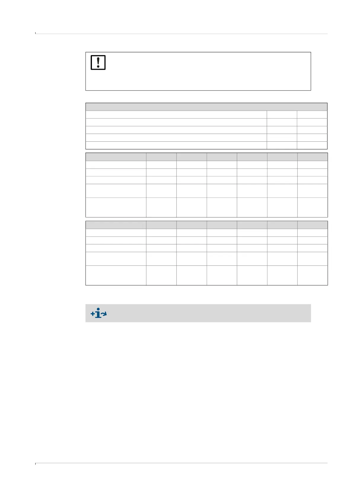
[1] The value increases by 1 DN when using meters with 2D / SD overall length.
[2] Class 0.5 is only achieved for the 8-path meter in this configuration.
NOTICE:
During operation, it is imperative to use the same flow conditioner as well
as the same pipes, in the same orientation as when calibrating the meter.
Mark the pipes and flow conditioner to indicate the flange alignment at the
time of calibration.
Configuration 1 (A)
OIML R137 A D
Class 1.0 7 DN 10 DN
Class 0.5 7 DN
2
10 DN
2
AGA Report 9 3rd Edition, July 2017 A D
“Metering package performance” according to Appendix C with CPA 50E 7 DN 10 DN
Configuration 2 (B1)
OIML R137 A B C D E F
Class 1.0 5 DN 2 DN 3 DN 5 DN 3 DN 2 DN
Class 0.5 7 DN 2 DN 5 DN 10 DN 8 DN 2 DN
AGA Report 9
3rd Edition, July 2017
A B C D E F
“Metering package perfor-
mance” according to
Appendix C with CPA 50E
10 DN 5 DN 5 DN 10 DN 5 DN 5 DN
Configuration 2 (B2)
OIML R137 A B C D E F
Class 1.0 6 DN 2 DN 4 DN 6 DN 4 DN 2 DN
Class 0.5 7 DN 2 DN 5 DN 10 DN 8 DN 2 DN
AGA Report 9
3rd Edition, July 2017
A B C D E F
“Metering package perfor-
mance” according to
Appendix C with CPA 50E
10 DN 5 DN 5 DN 10 DN 5 DN 5 DN
The maximum gas velocity in the pipe is limited to 40 m/s in configurations
with flow conditioner.