52 FLOWSIC600-XT · Operating Instructions · 8018846/1BHP/V2-1/2021-05 · © SICK Engineering GmbH
Installation
Subject to change without notice
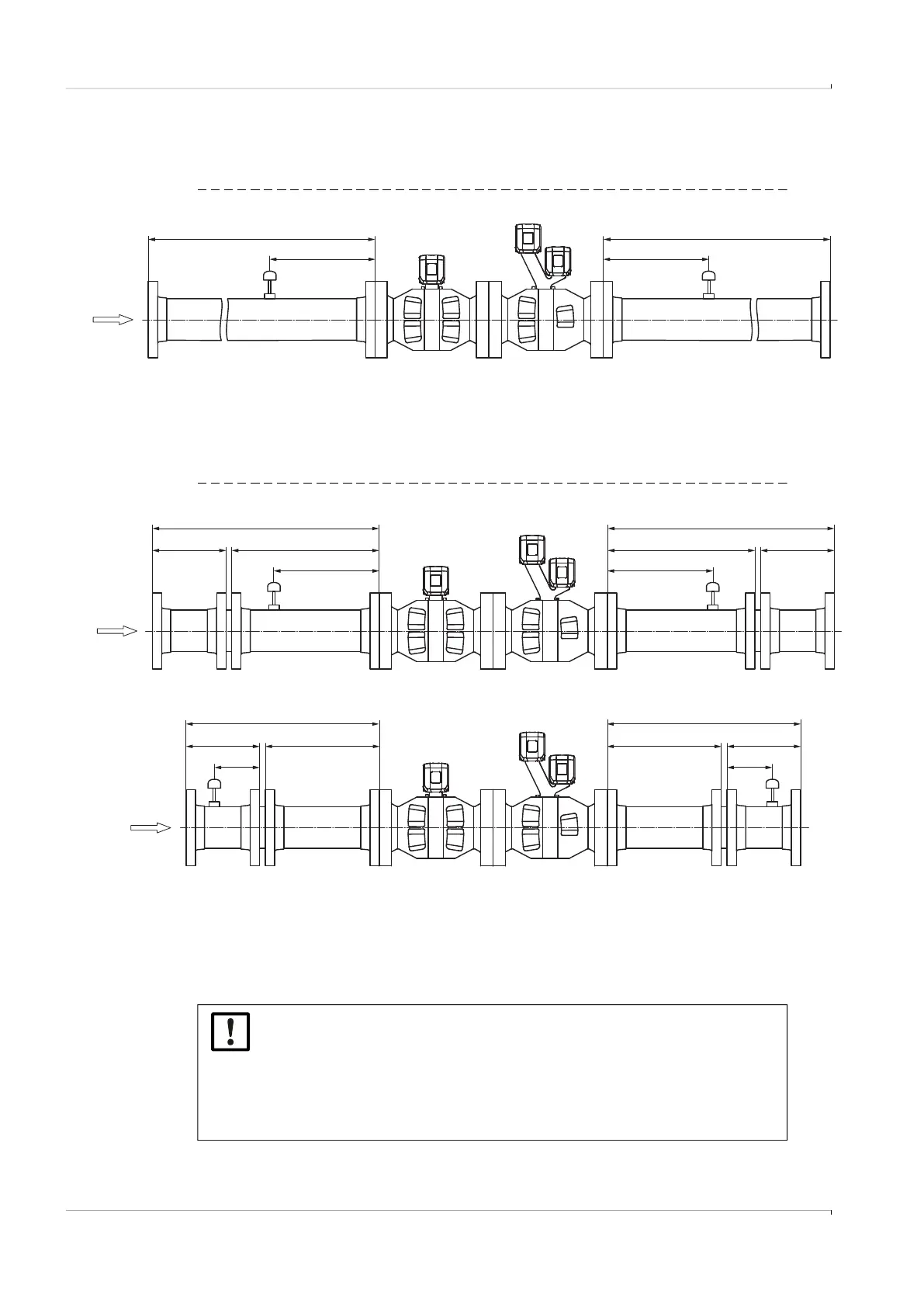
Flange-to-flange bidirectional
Fitting the FLOWSIC600-XT for bidirectional flange-to-flange use.
Fig. 23 Bidirectional flange-to-flange use without flow conditioner (configuration A)
Fig. 24 Bidirectional flange-to-flange use with flow conditioner (configuration B)
A
3 ... 5 DN
≥ A
1
3
2
≥ D
3 ... 5 DN
3
1. FLOWSIC600-XT (8 paths)
2. FLOWSIC600-XT (4+1 paths)
3. Alternative temperature measuring points
NOTICE:
Installation configuration (B) with the flow conditioner refers exclusively to SICK
conditioner types (according to SICK documents 9211778 and 9211779).
When using conditioner types CPA 50E or 55E, a distance between the condi-
tioner and meter of at least 5DN inlet length must be considered. When other
conditioners are used, the installation configuration can be different and must
be agreed with SICK.
3 ... 5 DN
≥ C≥ B
1
3
4
B1
2
1 DN
≥ C≥ B
1
3
4
B2
2
4
4
3
3
≥ E ≥ F
3 ... 5 DN
≥ F≥ E
1 DN
≥ A
≥ D
≥ A
≥ D
1. FLOWSIC600-XT (8 paths)
2. FLOWSIC600-XT (4+1 paths)
3. Alternative temperature measuring points
4. SICK flow conditioner