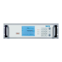
Product description
FLOWSIC600-XT · Operating Instructions · 8018846/1BHP/V2-1/2021-05 · © SICK Engineering GmbH 19
Subject to change without notice
If a geometry correction is to be made in the volume converter, it is important to make the
correct settings and to follow the procedure below.
1 Before calibrating the meter:
▸
Set α
T
and α
p
in the meter registers to “0”.
– Register No. 7422 … CC_DiameterPress Set value to “0”
– Register No. 7424 … CC_DiameterTemp Set value to “0”
▸
Set the fixed pressure vale in the meter equal to the nominal calibration pressure
(p
fix
= p
cal
).
▸
Set the temperature fixed value in the meter to the nominal calibration temperature
(T
fix
= T
cal
).
2 Calibrate the meter.
▸
Perform the adjustment using the preferred correction method.
▸
Check the adjustment accordingly.
3 During meter commissioning:
▸
Set the pressure fixed value in the meter equal to the average absolute operating
pressure (p
fix
= p
op
).
▸
Set the fixed temperature value in the meter equal to the average operating
temperature (T
fix
= T
op
) for Reynolds number correction in the flow meter.
4 The actual temperature and pressure difference in the calibrated state must be
calculated for the geometry correction in the volume converter according to the
equations:
– Δ
T
= T
op
– T
cal
(T
op
in °C)
– Δ
p
= p
op
– p
cal
(p
op
in bar(a))
Within the framework of individual national approvals, an access restriction
may prohibit modification of the substitute values when the parameter locking
switch is closed.
 Loading...


