SYSTEM DESCRIPTION 3
8026362 / V1-0/2022-03|SICK
Subject to change without notice
SUPPLEMENTARY OPERATING INSTRUCTIONS | VMS4100/5100
• In an area before and after the measuring station, the conveying equipment must run
straight and evenly. The conveyor belt must have a uniform and flat surface. The front
and back area corresponds to the maximum length of the measuring object (see also
section 3.7 Nominal operating conditions).
NOTE! If the specific installation position of the measuring system fails to satisfy this
requirement, the maximum length for the measuring objects must be restricted
accordingly and indicated on the identification label (see section 3.8.1 Information
labels).
• Positive or negative slopes of the conveying equipment must be kept flat enough to
prevent the measuring objects from sliding.
• The conveying equipment must not have any shiny or reflective surfaces. This can have
a negative impact on the measurement results.
• No guides for measuring objects may be installed in the vicinity of the measuring
station.
3.9.3 Mounting requirements
▸
Use a stable frame that is secured to prevent twisting and has sufficient load-bearing
capacity.
▸
Attach the frame to the conveying system in such a way that it cannot shake or vibrate.
▸
Align the frame at a right angle to the conveying direction.
NOTE! Use Item aluminum profiles.
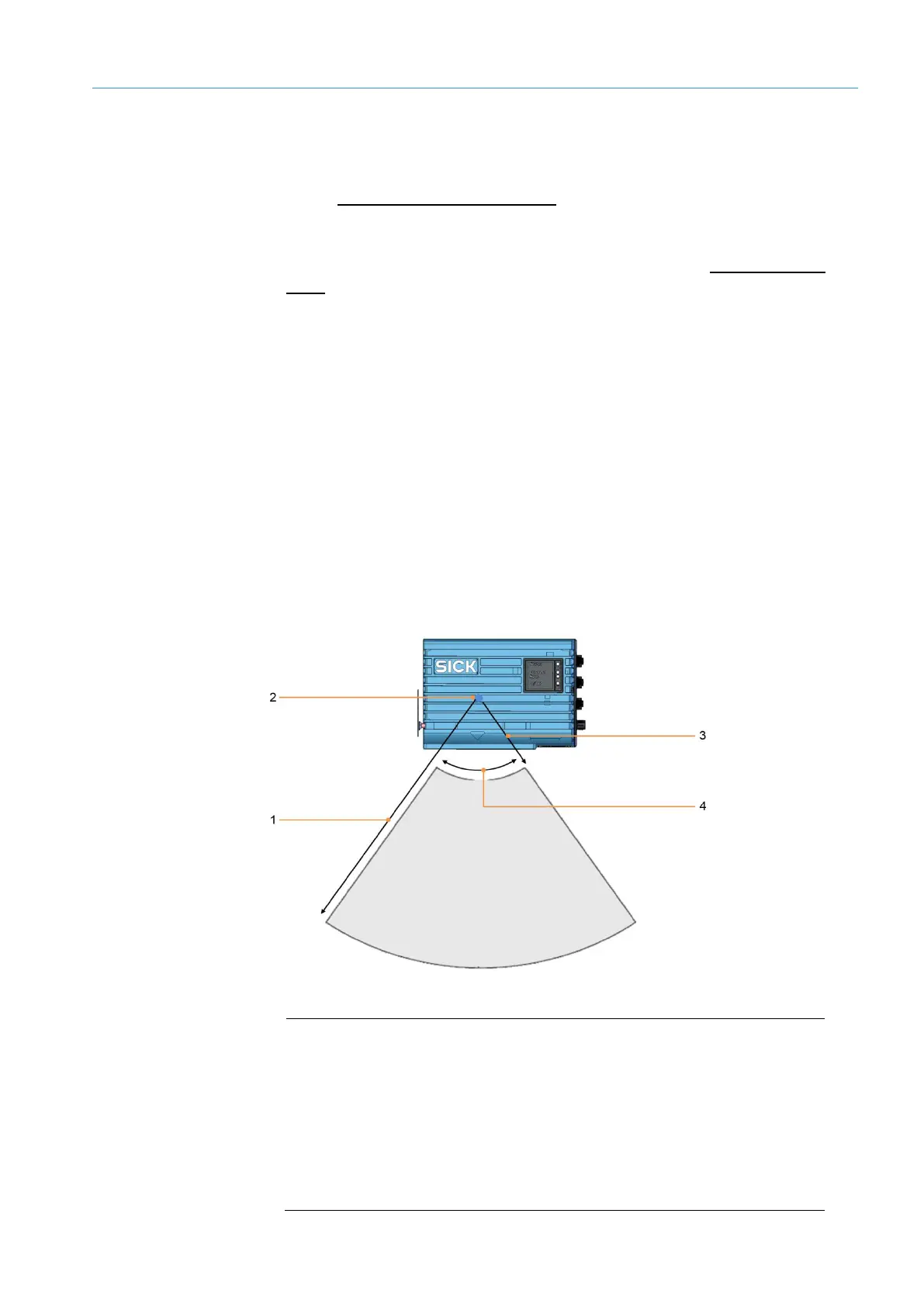
Fig. 60: Working range of the LMS4x21
Legend
1 Maximum working sensing range: 3 m
2 Zero point of the distance measurement. In the delivery state, this point
is the origin of the laser (marked with a point on the upper and lower
side of the housing).
3 Minimum distance between the zero point of the measurement and the
measuring object: 900 mm
4 Aperture angle: 70°
General requirements
Frame
LMS4x21