EasyManuals Logo

SICK VMS4100 User Manual

SICK VMS4100
122 pages
To Next Page IconTo Next Page
To Previous Page IconTo Previous Page
Page #80 background imageLoading...
Page #80 background image
5 ELECTRICAL INSTALLATION
80
8026362 / V1-0/2022-03|SICK
SUPPLEMENTARY OPERATING INSTRUCTIONS | VMS4100/5100
Subject to change without notice
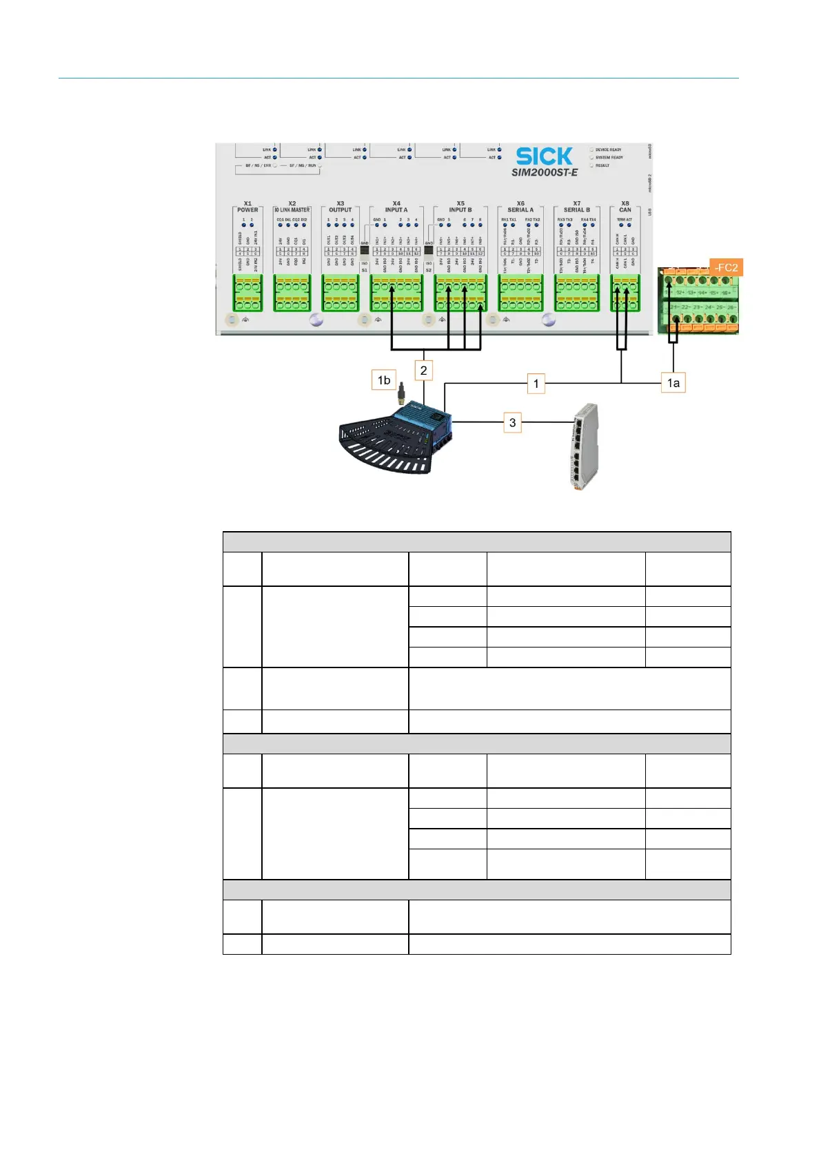
5.4.2 Connection of the 2D LiDAR sensor on LFT Ethernet switch
Fig. 77: Connection for the 2D LiDAR sensor on the SIM2000-2 Prime/LFT Ethernet switch
CAN bus/voltage supply
No.
Connection for the
LMS4x21
Wire color
SIM2000-2 Prime
terminal
Connection
1
1a
POWER CAN_IN
White
X8 CAN
1 CAN_H
Blue
X8 CAN
2 CAN_L
Red
-FC2
11 +
Black
-FC2
21 –
No. Connection for the
LMS4x21
1b POWER CAN OUT Terminator
Increment
No.
Connection for the
LMS4x21
Wire color
SIM2000-2 Prime
terminal
Connection
2 TACHO INPUT
Gray
X4 INPUT A
3 IN2+
Black
X5 INPUT B
2 IN5+
White
X5 INPUT B
4 IN6+
Blue
X5 INPUT B
12 GND
ISO (X5)
Ethernet
Connection for the
LMS4x21
Port on LFT Ethernet switch
3
Ethernet
1
Tab. 12: Connection of the 2D LiDAR sensor to the SIM2000-2 Prime/LFT Ethernet switch

Table of Contents

Other manuals for SICK VMS4100

Questions and Answers:

Question and Answer IconNeed help?

Do you have a question about the SICK VMS4100 and is the answer not in the manual?

SICK VMS4100 Specifications

General IconGeneral
BrandSICK
ModelVMS4100
CategoryIndustrial Equipment
LanguageEnglish

Related product manuals