ELECTRICAL INSTALLATION 5
8026362 / V1-0/2022-03|SICK
Subject to change without notice
SUPPLEMENTARY OPERATING INSTRUCTIONS | VMS4100/5100
5.6 Connection of the incremental encoder
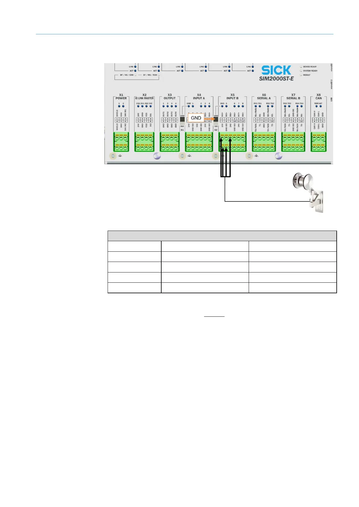
Fig. 80: Connection for the incremental encoder
Encoder signal
Wire color Terminal Connection
Black X5 INPUT B 1 IN5+
White X5 INPUT B 3 IN6+
Brown X5 INPUT B 7 24 V
Blue X5 INPUT B 8 GND ISO (X5)
Tab. 15: Connection for the incremental encoder
• If the encoder signal comes from an external source, the switching input can be
connected to the controller in a volt-free manner.
• In this case, the DIP switch S2 must be set to GND_ISO (X5).
• The connection with terminal 7 (24 V) can be omitted.
External
encoder signal