EasyManuals Logo

SICK VMS4100 User Manual

SICK VMS4100
122 pages
To Next Page IconTo Next Page
To Previous Page IconTo Previous Page
Page #75 background imageLoading...
Page #75 background image
ELECTRICAL INSTALLATION 5
75
8026362 / V1-0/2022-03|SICK
Subject to change without notice
SUPPLEMENTARY OPERATING INSTRUCTIONS | VMS4100/5100
5.1 Connection overview
5.1.1 Cabinet without LFT Ethernet switch
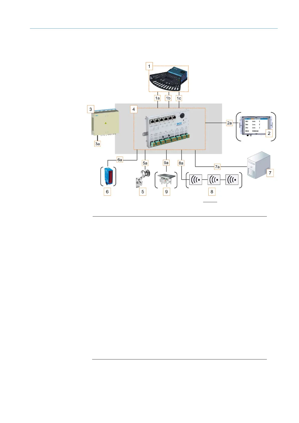
Fig. 72: Connection overview for VMS4100/5100 - cabinet without LFT Ethernet switch
Legend
1
2D LiDAR sensor
1a
CAN bus
1b Increment
1c Ethernet
2
LFT display - VMS5100 only
3a
Ethernet
3
Cabinet
3a
Feed 100 ... 264 V AC / 50 ... 60 Hz
4 SIM2000-2 Prime controller
5
Incremental encoder
5a
Encoder signal
6
Photoelectric retro-reflective sensor (optional)
6a
Trigger signal
7 Customer server
7a
Data output via Ethernet, fieldbus, or serial connection
8
Reading station (optional)
8a
CAN bus
9
Weighing station (optional)
9a
Data connection

Table of Contents

Other manuals for SICK VMS4100

Questions and Answers:

Question and Answer IconNeed help?

Do you have a question about the SICK VMS4100 and is the answer not in the manual?

SICK VMS4100 Specifications

General IconGeneral
BrandSICK
ModelVMS4100
CategoryIndustrial Equipment
LanguageEnglish

Related product manuals