7 MAINTENANCE AND REPAIR
8026362 / V1-0/2022-03|SICK
SUPPLEMENTARY OPERATING INSTRUCTIONS | VMS4100/5100
Subject to change without notice
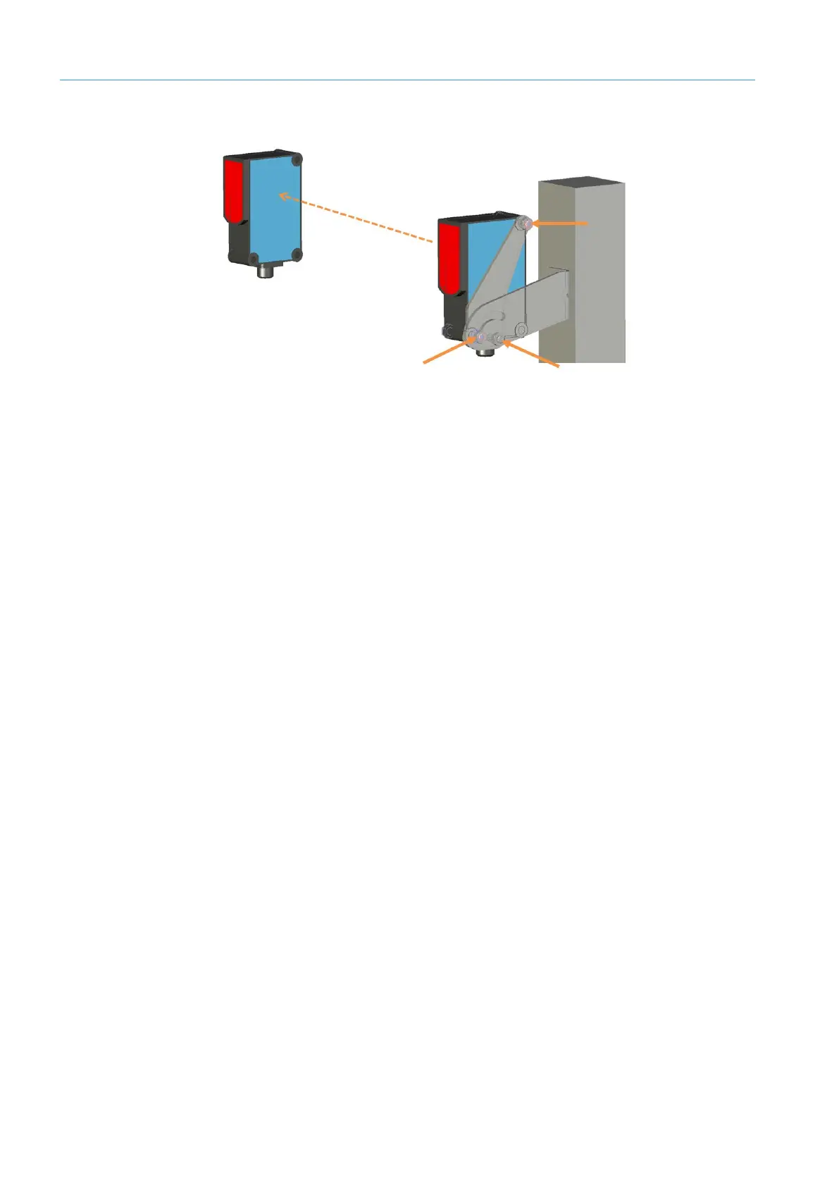
7.2.4 Replacing the photoelectric retro-reflective sensor (optional)
Fig. 93: Removing the object detection photoelectric sensor
▸
Unscrew the M12 plug connection from the male connector on the object detection
photoelectric sensor.
▸
Remove the clinch stud.
▸
Unscrew the hexagon screws.
NOTE! Hold the object detection photoelectric sensor firmly with one hand during the
procedure.
▸
Remove the defective photoelectric sensor from the mounting bracket.
▸
Screw the replacement device onto the mounting bracket.
▸
Secure the replacement device using the clinch stud.
▸
Screw the M12 plug connection onto the male connector on the object detection
photoelectric sensor.
▸
Align the photoelectric sensor correctly on the reflector. The reflector must be
positioned within the beam path of the object detection photoelectric sensor.
Check that the object detection photoelectric sensor is operating correctly.
Replacing the
component