(1)
CAN bus is available with device version 9.100 and higher.
Related topics
X3, X4 – Bus Connection, page 132
Connection Diagram, page 186
12.6 X5 – DIO
Digital inputs and digital outputs
The available functions of the digital inputs and outputs are different depending on the
drive function. You can set the desired function in the software drivemaster2.
Note
Some functions of the inputs/outputs are not available with older hardware or software
versions.
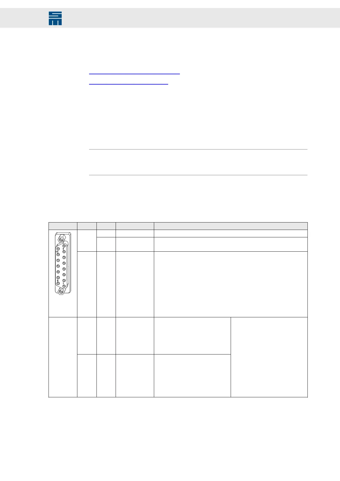
12.6.1 Digital Inputs / Outputs – SERVO / VECTOR (SVC)
15-pole female submin D connector
X5 Pin I/O Name Configurable functions
1 I/O GND Logic supply
2 I IN0/ RON
▸
No function
▸
Switch on
3 I IN1/ STOP
▸
No function
▸
Quick stop type 1 (with slow down ramp)
▸
Quick stop type 2 (with quick stop ramp)
▸
Quick stop type 3 (at current limit)
▸
Quick stop type 4 (speed enable)
▸
Quick stop type 5 (with slow down ramp and controller off)
▸
Quick stop type 6 (with quick stop ramp and controller off)
▸
Operation enable
▸
Operation enable with error reset
▸
MOP up
▸
MOP down
4 I IN2/ LIMIT-
▸
Neg. limit switch type 1 (speed
contr. as p-contr.)
▸
Neg. limit switch type 2 (speed
contr. as pi-contr.)
▸
Internal target value Bit 3
▸
Parameter set Bit 0
5 I IN3/ LIMIT+
▸
Pos. limit switch type 1 (speed
contr. as p-contr)
▸
Pos. limit switch type 2 (speed
contr. as pi-contr)
▸
Docking function
▸
Internal target value Bit 2
▸
Parameter set Bit 1
▸
No function
▸
Operation enable
▸
Operation enable with error reset
▸
Error reset
▸
External hardware OK
▸
Speed direction
▸
Teach no-load current
▸
MOP up
▸
MOP down
109Drive System SD2 - Hardware Description
Connector Pin Assignment
 Loading...