Connector Pin Assignment
12.23 X69 (1, 2) – External Ballast Resistor
2-pole PCB terminal block ZFKDS 10, 15 mm (Phoenix)
X69 (1, 2) Pin Name Meaning
1 BRexternal External ballast resistor BRexternal
2 UB+ DC link voltage for external ballast resistor BRexter-
nal
Specification of terminal connections:
▸
Conductor cross-section solid/stranded: 0.2 to 16 mm² (AWG 24 - AWG 6)
▸
Stripping length of the conductors: 12 mm
Related topics
Connection Diagram, page 186
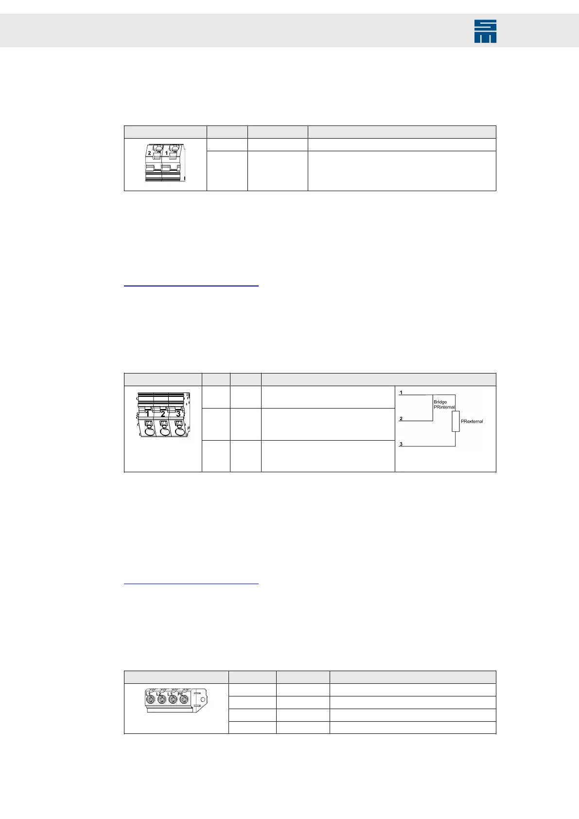
12.24 X70 (1, 2, 3) – External Precharge Resistor
3-pole PCB terminal block ZFKDS 10, 10 mm (Phoenix)
X70 (1, 2, 3) Pin Name Meaning
1 Uin Connector pin for precharge switch-
ing transistor
2 PRint-
ernal
Connector pin for wire strap to pin 1
to activate the internal precharge re-
sistor PRinternal
3 PRex-
ternal
Connector pin for external precharge
resistor PRexternal between pin 1
and pin 3
Specification of terminal connections:
▸
Conductor cross-section solid: 0.2 to 6 mm² (AWG 24 - AWG 10)
▸
Conductor cross-section stranded: 0.2 to 4 mm² (AWG 24 - AWG 10)
▸
Stripping length of the conductors: 10 mm
Related topics
Connection Diagram, page 186
12.25 X71 – Mains Supply PS2
4-pole screw terminal (Weidmüller)
X71 Pin Name Meaning
1 L1 Main supply
2 L2 Main supply
3 L2 Main supply
4 PE Protective conductor
Specification of terminal connections:
126 Drive System SD2 - Hardware Description
 Loading...