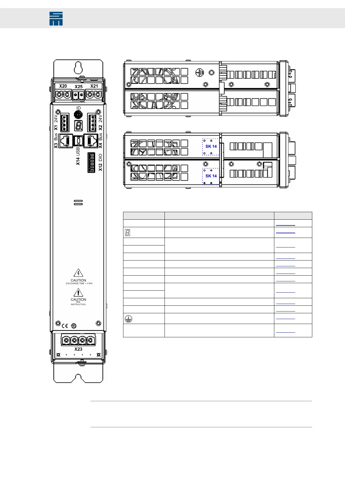
9.3.3 Connectors
Fig. 68: Front view
Fig. 68: Front view
Fig. 69: Top view
Fig. 69: Top view
Fig. 70: Bottom view
Fig. 70: Bottom view
Connector Meaning Description
ID Address selection switch of device page 107
Status display page 164
X1 24 V
X2 24 V
Power bus: 24 V logic supply and status message
from the power supply
page 107
X3 Bus Bus inputs page 108
X4 Bus Bus outputs page 108
X12 DIO Digital inputs / digital outputs page 116
X14 USB USB interface for parameterization page 118
X20
X21
DC link output page 118
X23 Mains supply of power supply unit page 121
X25 External ballast resistor page 121
Device housing ground page 151
SK 14
Mounting holes for shield connection clamp SK 14
by Phoenix
page 152
Note
You can order the suitable connector kit for the device variant 0362191y at SIEB & MEY-
ER under article number 32299540.
93Drive System SD2 - Hardware Description
Power Supply Unit PS2