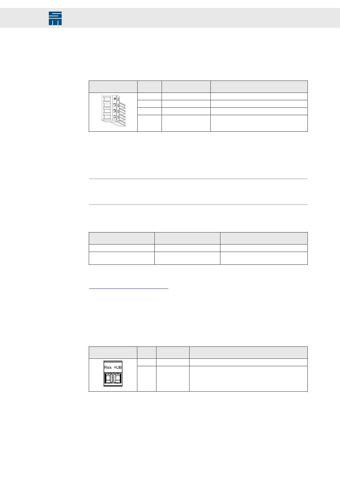
12.18 X23 – Mains Supply PS2
4-pole Power Combicon connector, suitable for mating connector PC 6/ 4-ST-10,16
(Phoenix)
Mating con-
nector X23
Pin Name Meaning
1 PE Protective conductor
2 L3 Main supply
3 L2 Main supply
4 L1 Main supply
Specification of terminal connections:
▸
Conductor cross-section solid: 1.5 – 10 mm²
▸
Conductor cross-section stranded: 1.5 – 6 mm²
▸
Tightening torque: 1.2 – 1.5 Nm
Note
Consider that the conductor cross-section to be used for your application depends on
the total load of the power supply unit.
The device variant 0362191y is designed for usage with the following shield connec-
tion clamps. (The terminals are not included in the scope of supply.)
Manufacturer Article number of the manu-
facturer
Description
Phoenix Contact 302 51 89 Shield connection clamp SK 20
WAGO Innovative Connec-
tions
791-117 Shield (screen) clamp
Related topics
Connection Diagram, page 186
12.19 X25 – External Ballast Resistor
2-pole Power-Combicon terminal, suitable for mating connector PC 4/ 2-ST-7,62
(Phoenix)
Mating con-
nector X25
Pin Name Meaning
1 BRexternal External ballast resistor BRexternal
2 UB+ DC link voltage for external ballast resistor BRexternal
Specification of terminal connections:
▸
Conductor cross-section solid/stranded: 1.5 to 4 mm²
▸
Tightening torque: 0.5 to 0.6 Nm
121Drive System SD2 - Hardware Description
Connector Pin Assignment
 Loading...