Connector Pin Assignment
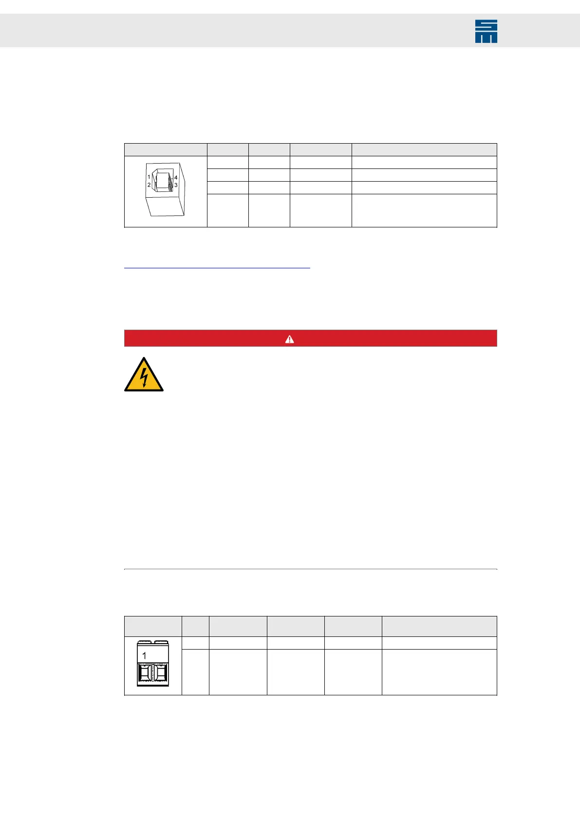
12.15 X14 – USB (Parameterization)
Communication interface to the connected PC
4-pole female USB connector, type B
X14 Pin I/O Name Description
1 - VCC 5 V voltage supply for USB
2 I/O DN Data−
3 I/O DP Data+
4 I/O GND Ground
Related topics
chapter C “Connection Diagram”, page 186
12.16 X20, X21 – DC Link Connectors
DANGER
High voltages in the intermediate circuit
Note that even after the power supply unit has been switched off high volt-
ages may occur in the intermediate circuit of the complete system that can
cause serious injuries.
→ Wait until the intermediate circuit is fully discharged before cutting the
connections of the intermediate circuit ("capacitor discharge").
→ Take the following steps before working on the device or on the inter-
mediate circuit:
→ Disconnect the power supply unit definitely from the mains supply.
→ Wait until the discharge time of the of the DC link capacities has ex-
pired. It is longer than 4 minutes.
→ Ensure by measuring that the intermediate circuit is fully discharged.
→ Disconnect the intermediate circuit connections from the power sup-
ply.
→ Also consider general safety instructions before you continue working
on the device.
2-pole Power-Combicon connector, suitable for mating connector IPC 16/ 2-ST-10,16
(by Phoenix)
Mating con-
nector X20
Pin Coding Name Position Meaning
1 Coded UB- Left DC link -
2 - UB+ Left DC link +
118 Drive System SD2 - Hardware Description
 Loading...