12.11 X10 – Safety (STO)
Safety circuit and restart lock (STO)
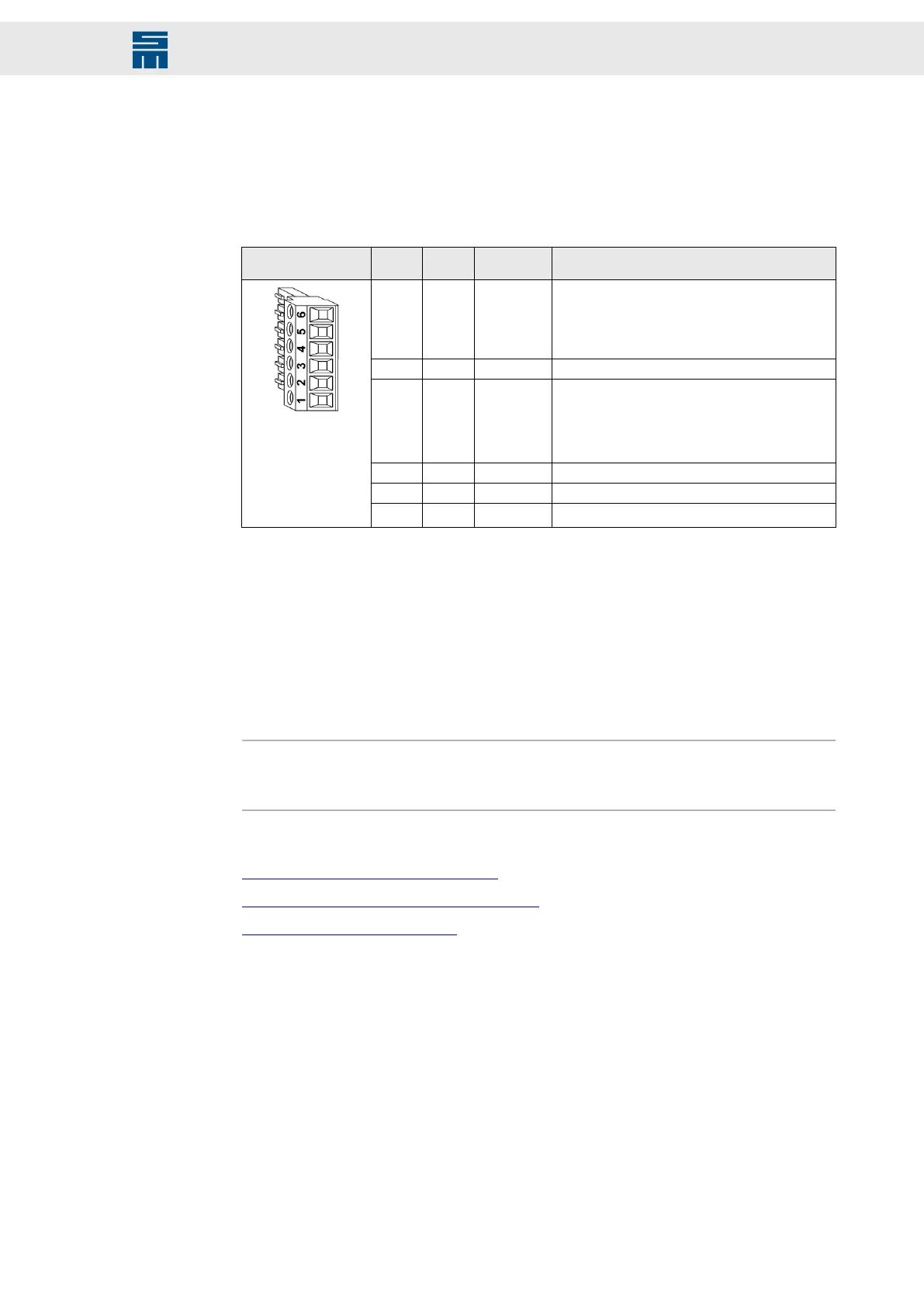
6-pole Mini-Combicon connector, suitable for mating connector MC 1.5/ 6-ST-3.81
(Phoenix)
Mating con-
nector X10
Pin I/O Name Meaning
1 I SAFEA /
OSSD1
Enable of the safety circuit
▸
Permanent load approx. 15 mA/24 V
▸
Startup peak current is negligible under nor-
mal conditions.
2 – GND Reference potential
3 I SAFEB /
OSSD2
Enable of the safety circuit
▸
permanent load approx. 160 mA/24 V
▸
Startup peak current per device can exceed
8 A/24 V during the first 2 ms.
(2)
4 O OUT3_B Output 3 of drive B
5 O OUT3_A Output 3 of drive A
6 O
24 V
(1)
Logic voltage 18 to 28 volts (uncontrolled)
(1)
The 24 V output is not suited to supply external safety circuits because an external voltage source is
necessary to comply with the applicable standards. If the safety function (STO) is not required, this voltage
is only used to bridge the pins 1 and 3.
(2)
The startup peak current of current devices is internally limited to 2 A/ 24 V per device and then applies
up to 20 ms.
Specification of terminal connections
▸
Conductor cross-section solid/stranded: 0.14 to 1.5 mm²
▸
Tightening torque: 0.22 to 0.25 Nm
Note
The power supply unit is only activated when SAFEA and SAFEB are connected. If the
safety function (STO) is not required, pin 1 and pin 3 must be bridged to pin 6.
Related topics
X10 – Safety Circuit (STO), page 147
Safety circuit / restart lock (STO), page 176
Connection Diagram, page 186
115Drive System SD2 - Hardware Description
Connector Pin Assignment
 Loading...