Connection Examples
13.9 X11 – Temperature Sensor of the Motor
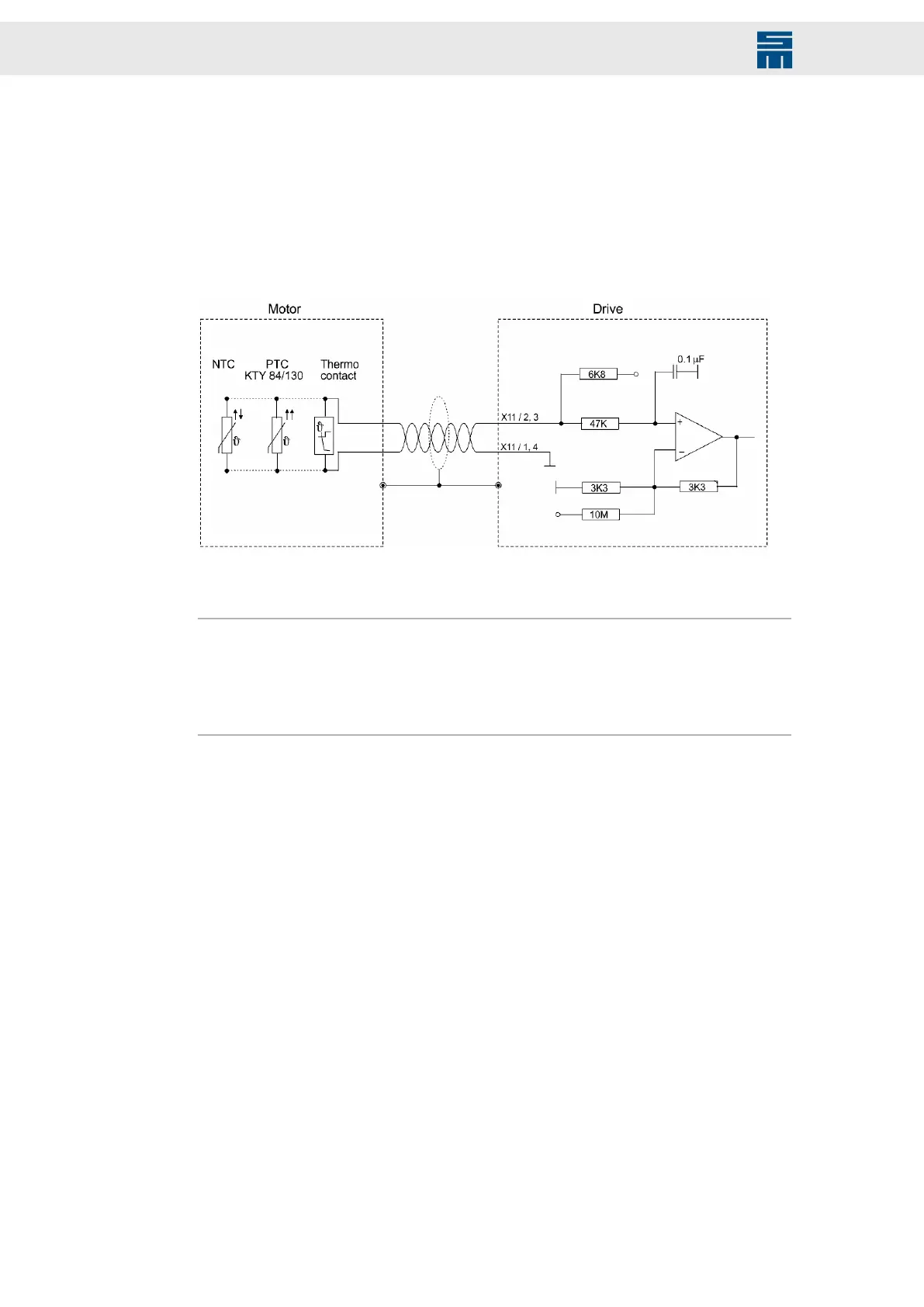
INPUT/OUTPUT: The thermal motor protection is evaluated via these connectors.
The drive amplifier supports evaluating the temperature monitoring integrated in the mo-
tor. The NTC/PTC behavior of the monitoring is defined in the software (motor parame-
ters). The controller is deactivated as soon as the critical motor temperature is reached.
You can configure “None”, “PTC / Thermo switch”, “NTC”, “KTY84/130”, “KTY83/122”
and “PT1000”.
Fig. 89: Temperature Sensor of the Motor
Fig. 89: Temperature Sensor of the Motor
The temperature sensor must have an internal resistor between 250 Ω and 2 kΩ.
Note
If no motor temperature sensor is connected, the input must be connected with GND.
The connectors X5 (DIO), X8 (Resolver) and X9 (feedback) also provide an input for the
temperature sensor each. Anyway, only one motor temperature sensor per drive side is
to be connected to one of the four connectors.
148 Drive System SD2 - Hardware Description
 Loading...