Remove device cover: delivery until June 2019
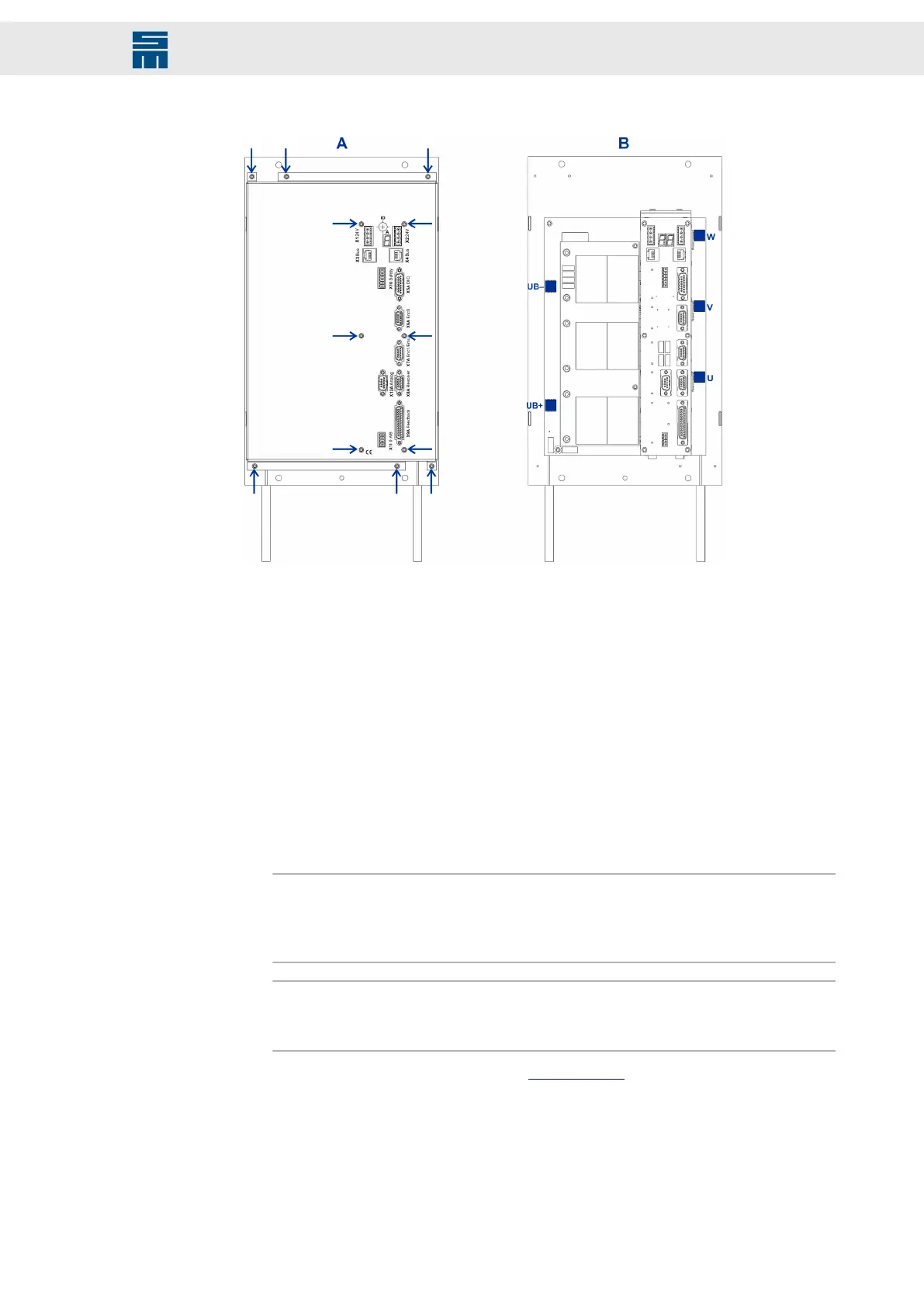
➮ Remove the 12 screws (lens head screws 3×6, DIN 7985, zinc coated, Torx) of the
device cover [picture A].
➮ Remove the device cover carefully. You find the connectors for the DC link (UB+,
UB−) and the motor (U, V, W) on the left and on the right side of the device. They
are implemented as individual power bushes [picture B].
Connect cables
➮ Connect the 5 cables for the DC link and the motor phases to the respective power
bushes. Use ring cable lugs for this purpose.
a. Cable cross-section = 50 mm²
b. Ring cable lug = M6
c. Tightening torque = 5 Nm
Note
The cables of the motor phases must lie on top of each other in the housing. Oth-
erwise, the can cause interferences. For that reason, you must connect phase U at
first, then phase V and phase W at last.
Note
The protective conductor PE for the motor connection must be connected to the
heat sink plate via an M6 screw.
Also refer to the connection example Motor Phases.
Fasten device cover
➮ Replace the device cover. Take care to feed the DC link cables (UB+, UB−) and the
motor cables (U, V, W) through the intended openings as shown below.
129Drive System SD2 - Hardware Description
Connector Pin Assignment
 Loading...