General Information Regarding the Wiring
▸
The cable shields must be connected to the connector shell inside of the connec-
tors. In the switch cabinet they should be connected to a ground bus.
▸
Cable shields not ending in a connector inside of the switch cabinet such as motor
cables must be connected to the ground bus.
▸
Both ends of the shield of shielded cables must generally be connected to the shell.
The line cross-sections should be selected carefully so that the maximum admissible
current is not exceeded at the maximum ambient temperature (see technical data). DIN
VDE 0298-4 defines the admissible values for the individual line cross-sections, which
must absolutely be taken into account.
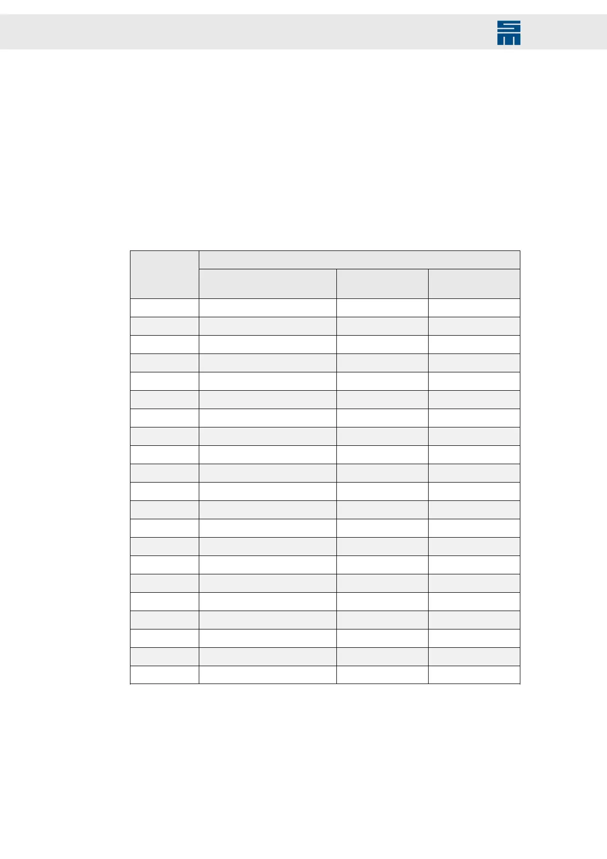
The current carrying capacity in connection with the line cross-section of copper con-
ductors isolated with PVC or cables according to DIN VDE 0298-4 for different types of
wiring are indicated in the following table: All values are related to an ambient temper-
ature of +40 °C and an operating temperature at the conductor of 70 °C.
Admissible current I [A]
Tab. 2: Current carrying capacity according to DIN VDE 0298-4
Conductor
cross-sec-
tion A [mm²]
B2 wiring
(1)
E wiring (3 ca-
ble leads)
(2)
F wiring (3 ca-
ble leads)
(3)
0.75 7.6 10.4 –
1.00 9.6 12.4 –
1.50 12.2 16 –
2.50 16.5 22 –
4 23 30 –
6 29 37 –
10 40 52 –
16 53 70 –
25 67 88 96
35 83 110 119
50 100 133 145
70 130 171 188
95 150 207 230
120 175 240 268
150 – 277 309
185 – 317 356
240 – 374 422
300 – 433 488
400 – – 570
500 – – 652
630 – – 744
Tab. 2: Current carrying capacity according to DIN VDE 0298-4
(1)
B2 wiring: wiring in installation tubes or closed installation channels.
(2)
E wiring: Free wiring of one cable with a min. distance of 0.3 × cable diameter to the wall.
(3)
F wiring: Free wiring of several cables with a min. distance of 1 × cable diameter to the wall.
For detailed information refer to the standard IEC 60364-5-52 and the documents of the
cable manufacturer.
168 Drive System SD2 - Hardware Description
 Loading...