Operation
152/214 Revision 06 • INSTALLATION AND OPERATING INSTRUCTIONS • 8DB10 • 864-5091.9
37 Operating the three-position disconnector
The procedures described in this section apply to:
• Disconnectable voltage transformers or disconnectable busbar connections
• Top-mounted bus sectionalizer
• Switching operations on circuit-breaker panels
• Switching operations on bus sectionalizer panels
• Switching operations on bus coupler panels
37.1 Control elements and indicators
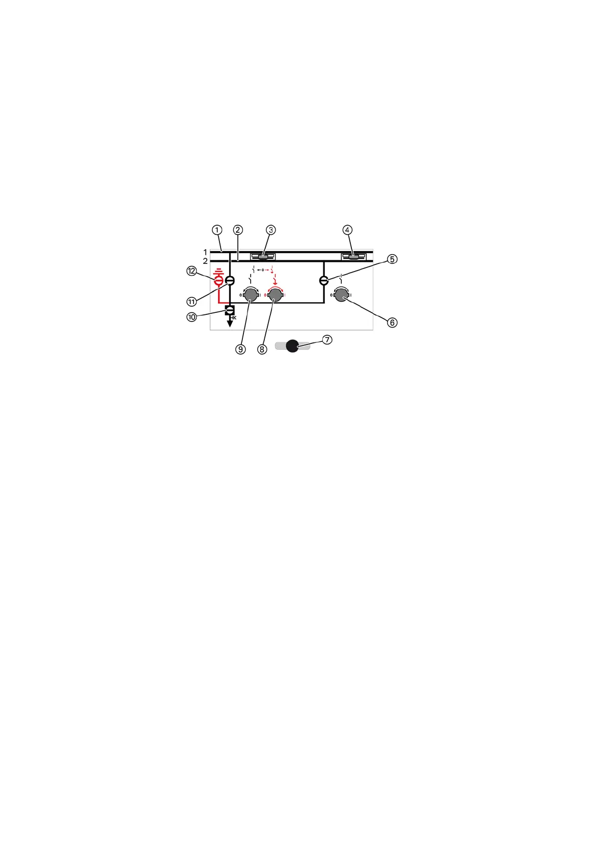
Control board on
the switchgear front
The manual switching operations DISCONNECTING or READY-TO-EARTH must be pre-selected
with the interrogation lever. The interrogation lever can only be operated if the associated
switching operation is permissible.
Fig. 175: Control board on the switchgear front
①
Busbar system 1
②
Busbar system 2
③
Control gate (three-position disconnector in busbar system 1)
④
Control gate (disconnector in busbar system 2)
⑤
Position indicator for disconnector in busbar system 2 (DISCONNECTING function)
⑥
Actuating opening for disconnector in busbar system 2 (DISCONNECTING function)
⑦
Selector gate for busbar system
⑧
Actuating opening for three-position disconnector in busbar system 1 (READY-TO-EARTH function)
⑨
Actuating opening for three-position disconnector in busbar system 1 (DISCONNECTING function)
⑩
Position indicator for circuit-breaker
⑪
Position indicator for three-position disconnector in busbar system 1 (DISCONNECTING function)
⑫
Position indicator for three-position disconnector in busbar system 1 (READY-TO-EARTH function)



 To Next Page