864-5091.9 • INSTALLATION AND OPERATING INSTRUCTIONS • 8DB10 • Revision 06 21/214
Description
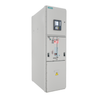
8.5 Switchgear panel
Fig. 4: 8DB10 circuit-breaker panel
①
Low-voltage compartment (standard heights: 850/1200 mm)
②
SIPROTEC bay controller (option)
③
Gas pressure manometer for circuit-breaker housing
④
Gas filling valve
⑤
Gas pressure manometer for three-position disconnector housing in system 1
⑥
Control and indication board for three-position disconnector with position indicator for circuit-breaker
⑦
Gas pressure manometer for three-position disconnector housing in system 2
⑧
Control and indication board for vacuum circuit-breaker
⑨
Capacitive voltage detecting system
⑩
Cable compartment
⑪
Frame



 To Next Page