Operation
192/214 Revision 06 • INSTALLATION AND OPERATING INSTRUCTIONS • 8DB10 • 864-5091.9
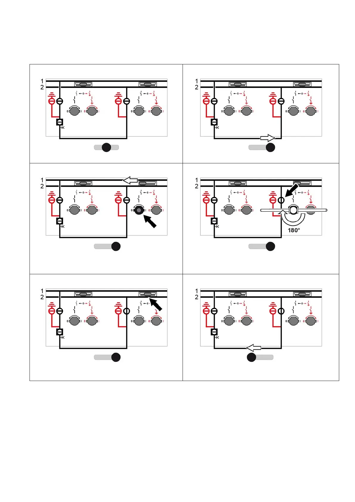
42.3 Switching operations in the bus coupler panel
Coupling systems 1 and 2
1
Initial situation
2
➭ Push the selector gate to the right.
3
➭ Push the right-hand control gate to the left.
4
➭ Switch the three-position disconnector to CLOSED position (insert the
operating lever for the DISCONNECTING function and turn 180°
clockwise).
5
➭ Remove the operating lever for the DISCONNECTING function.
The right-hand control gate returns to its initial position.
6
➭ Push the selector gate to the left.