Technical Data AddFEM
4-12
AddFEM
C79000–G8076–C900–03
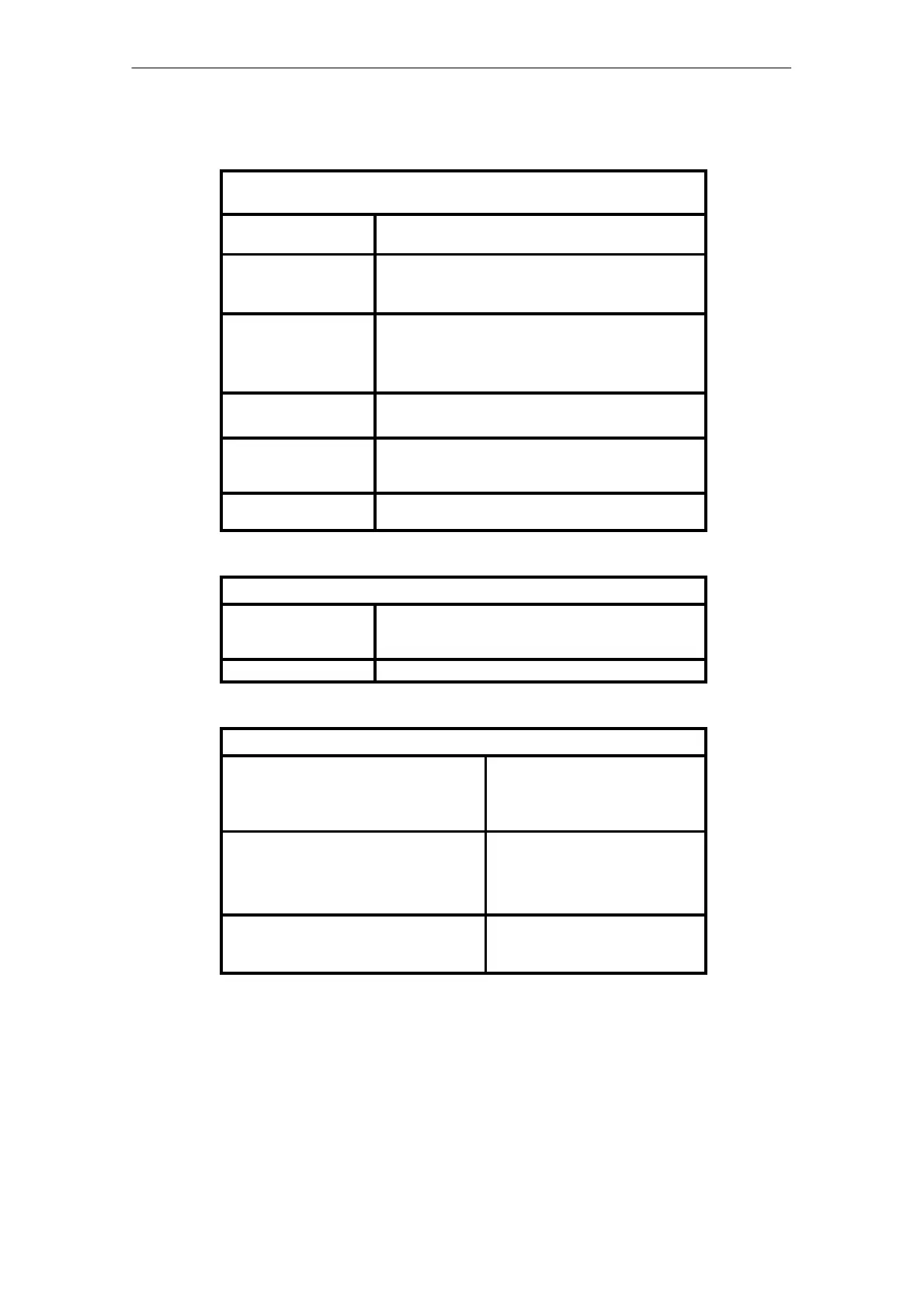
Cause for Redundancy Changeover at Module Redundancy
(Only 6DL3100–8AB/–8AC)
By priority (error weigh-
ting)
Cause
Forced reserve specifica-
tion
–Signal ZRV from the automation processor at failure of
the optical–fiber cable redundancy coupling
–Operating mode switch to STOP
Module fault –Memory test of the RAM data range
–Check sum across the program code in the
FEPROM/RAM
–Failure of the supply voltage/undervoltage
Central unit failure –Failure of the PROFIBUS DP
–Failure of the sign of life from the automation processor
Channel error –Channel error analog input, analog output, digital output
or failure of the 24 V DC load supply for the digital
outputs
Channel error weighting –Sum of the individual channel errors. All channel errors
have the same weighting
Response Times of the Error Recognition for Central Unit Failure
PROFIBUS–DP At activated response monitoring the monitoring time is
calculated from the corresponding values in the paramete-
rization telegram (refer to the PROFIBUS standard).
Sign of life 2 x automation processor cycle
Response Times of the Error Recognition for Channel Errors
1)
Analog inputs
Max. delay of the qualifier QU (Bit 0 of the re-
spective analog value AI 1...12) in the input
message
42.00 ms
Analog outputs
Max. delay of the qualifier AO 1 ... 8 in the in-
put message
12.667 ms
28.667 ms (at 6DL 3100–8AA till
Version 6)
Digital outputs or undervoltage load supply
Max. delay of the qualifier DO 1 ... 16 in the
input message
2.00 ms
1)
The error recognition times from the signal evaluation are a multiple of the cycle time due to error
filtering. The error filtering function ensures that disturbing pulses or the unique occurrence of an
error do not cause an error message.
Artisan Technology Group - Quality Instrumentation ... Guaranteed | (888) 88-SOURCE | www.artisantg.com
 Loading...


