AddFEM
Technical Data
4-15
AddFEM
C79000–G8076–C900–03
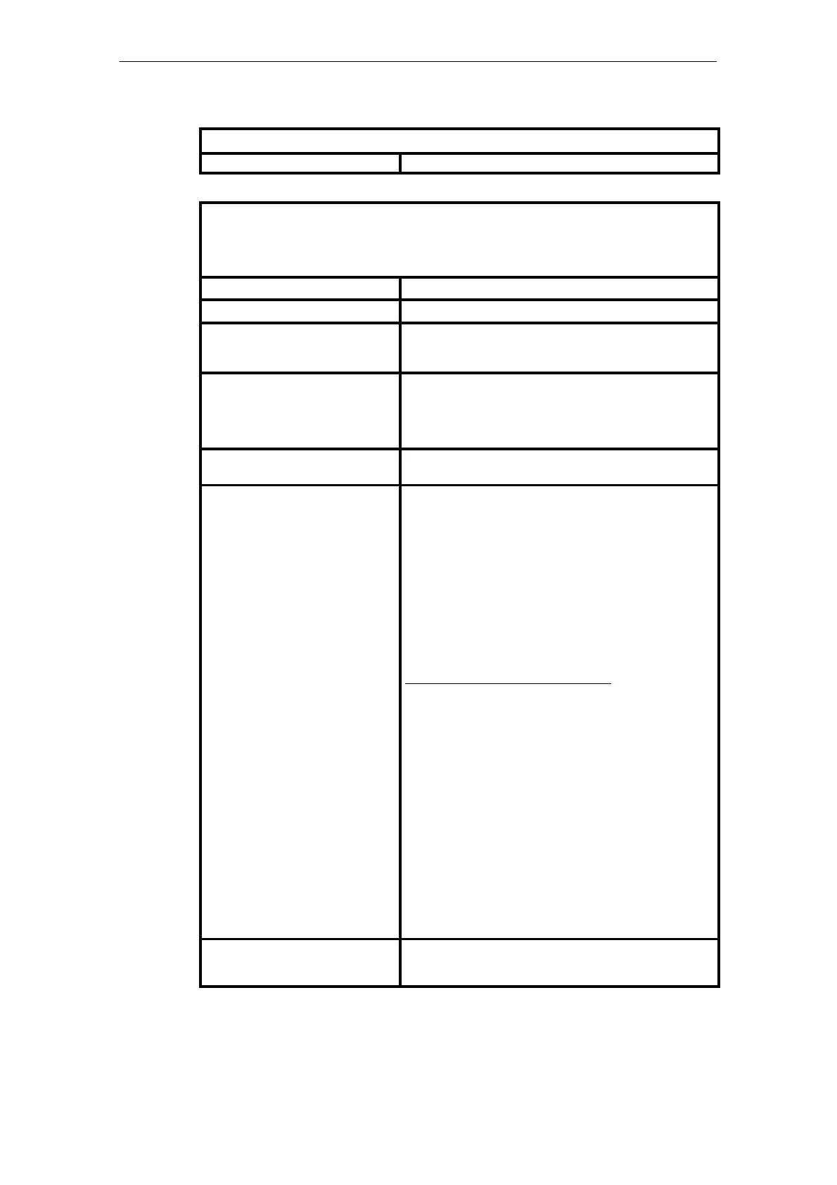
Reliability
MTBF Value to SN 29500 23 years at 40
o
C module ambient temperature
Electromagnetic Compatibility (EMC)
The specified values apply for the use of shielded process cables for analog signals. Digital signal ca-
bles can be laid without shielding. The values apply without the shielding effect of a cabinet and without
additional external protecting elements.
Stress Test values
Emitted interference Limit class A to VDE 60875, T11 ¢ EN 55011
RF effect on cables and cable
shields to ENV 50141
10 V 9 kHz to 80 MHz (with 80% amplitude modulation of
1 kHz)
Possible deviations for the analog input signals < 3%
RF effect on cables and cable
shields
To ENV 50140
To ENV 50204
10 V/m 80 MHz to 1 GHz to IEC 801–3 (with 80% amplitude
modulation of 1 kHz)
10 V/m 900 MHz (with 50% pulse modulation)
Burst pulses (rapid transient di-
sturbances) to IEC 1000–4–4
"2 kV on power supply cables and signal cables
High–energy single pulse
(1.2/50 ms pulse, surge) to
IEC 1000-4-5
Asymmetric interference
Symmetric interference
"2 kV On supply cables
"2 kV On signal lines
Type of crosstalk: At the unshielded binary signals
on the cable. On the shielded analog signals and
PROFIBUS DP on the cable shielding
"1 kV On the supply cables and signal cables
Information for 1.2/50 ms pulse/surge test:
The surge test simulates high–energy interference signals
which, depending on the ambient conditions (corresponding to
the standard) can be launched from cable lengths of approx.
10 m on and then superimpose themselves on the useful si-
gnals.
Since in the case of a surge the individual disturbing pulse
already lies within the sample frequency/cycle time of the mo-
dule, it is not possible to filter the interference signals suffi-
ciently by hardware means in the case of the very short cycle
times. Otherwise the corresponding useful signals would also
be filtered.
Therefore the 50– or 60–Hz filter should be activated at the
analog inputs if crosstalk from surge interference is to be ex-
pected on the signal cables due to the ambient conditions and
the cable lengths. When the filter is activated, the deviation at
the analog signals is reduced to less than 2% when surge
interference occurs. Without a filter brief individual deviations
of up to 60% are possible at the analog inputs.
Immunity to interference against
discharge of static electricity on hou-
sing and structural parts
"6 kV Contact discharge to IEC 1000-4-2
"8 kV Air discharge to IEC 1000-4-2
Artisan Technology Group - Quality Instrumentation ... Guaranteed | (888) 88-SOURCE | www.artisantg.com
 Loading...


