Technical Data AddFEM
4-22
AddFEM
C79000–G8076–C900–03
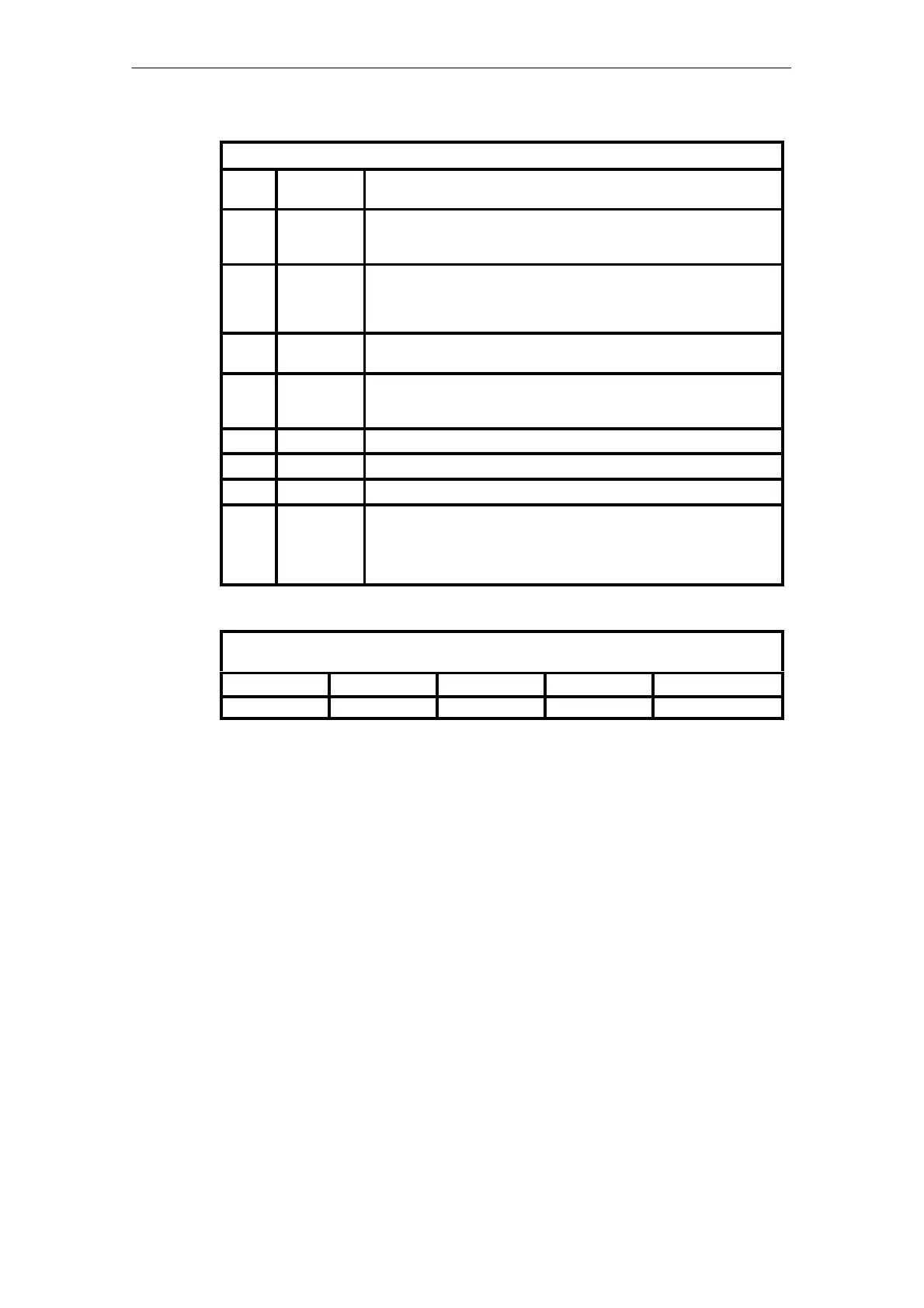
Error Weighting Structure
Bit
Pos.
Signal Meaning
7 ZRV Forced reserve specification manual
Is set when operating mode switch = STOP
e.g. due to repairs.
6 BGF Module fault
Grave fault. Hardware fault
e.g.: power failure, memory error, etc.
Restart of the AddFEM
5 ZTA Central unit failure
Higher–level fault. E.g. central unit or PROFIBUS DP failure.
4 KF Channel error
Lower–level or externally initiated channel fault. The number of channel
errors is supplied in the additional byte “Channel error weighting”.
3 RES Reserve
2 RES Reserve
1 RES Reserve
0 MRV* Master state specification request
The automation processor specifies the master state of the AddFEM as the
”higher–level referee”.
=1 –> Automation processor requests: AddFEM is reserve
=0 –> Automation processor requests: AddFEM is master
Legend: * Is not set in the error weighting via the PROFIBUS DP telegram
Floating–point Representation of the Counter Values in IEEE 754 Format (32 Bits =
4 Bytes):
Byte address +3 +2 +1 +0
Meaning SEEE EEEE EMMM MMMM MMMM MMMM MMMM MMMM
Meaning of the individual bits:
S Preceding sign bit
0: Positive / 1: Negative
E Exponent
Two’s–complement representation with a fixed offset of 127
M Mantissa 24 bits
The most significant bit is always 1 and is not represented. The least significant bit
of the exponent is displayed at the corresponding bit position.
Artisan Technology Group - Quality Instrumentation ... Guaranteed | (888) 88-SOURCE | www.artisantg.com
 Loading...


