Functions
8.1 BICO Technology
Control Units CU240S
Operating Instructions, 11/2006, A5E00766042B AA
8-5
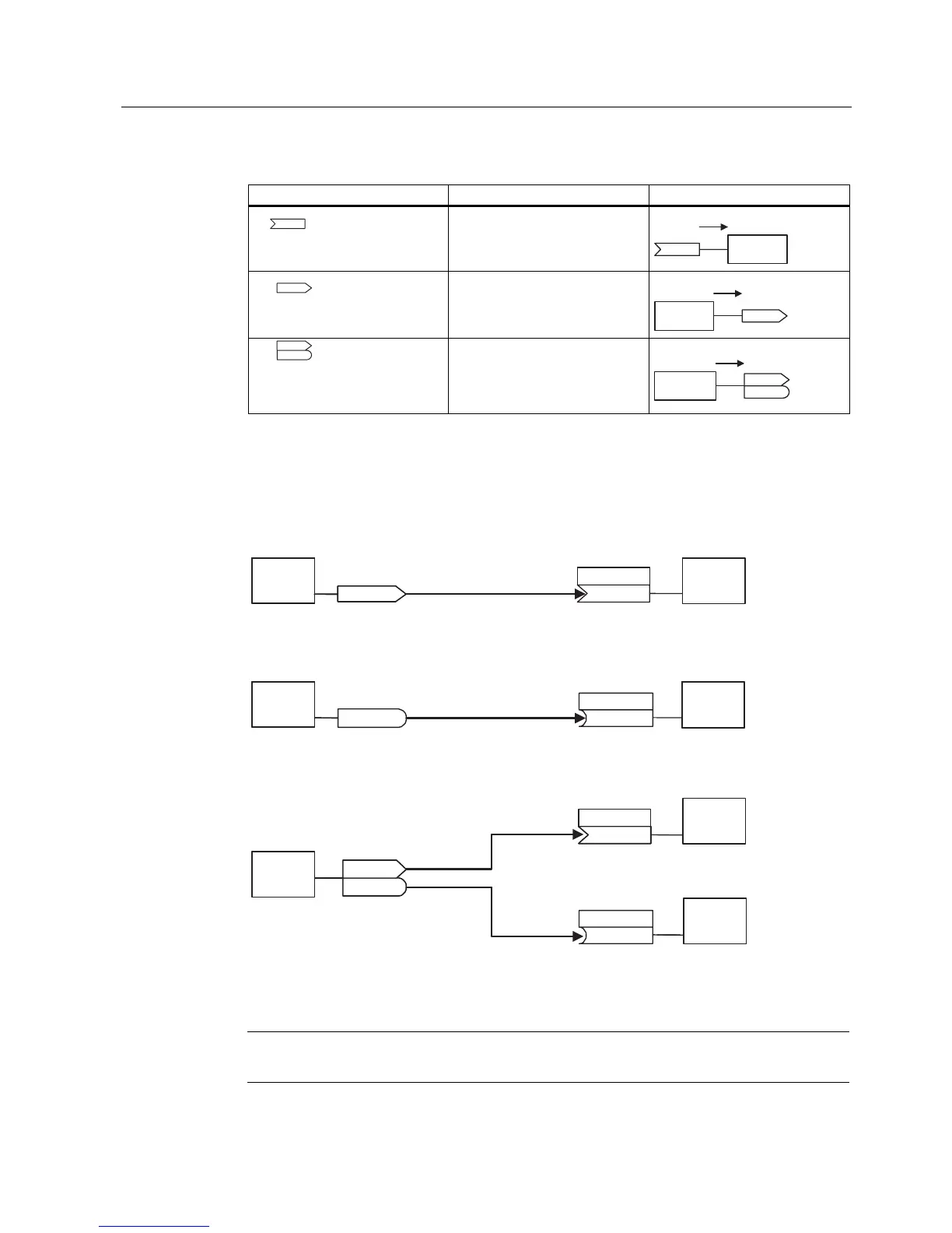
Table 8-4 Connectors
Abbreviation and symbol Name Function
CI Connector input
(signal sink)
In order to interconnect two signals, a BICO setting parameter (signal sink) must be
assigned the required BICO monitoring parameter (signal source). A typical BICO
interconnection is shown using the following examples (see figure below):
U
3
>@
3 >@
U
U
U
3
3
3
3
3
3
%,212))
&RQQHFWRURXWSXW&2 !&RQQHFWRULQSXW&,
%LQHFWRURXWSXW%2 !%LQHFWRULQSXW%,
&RQQHFWRURXWSXW%LQHFWRURXWSXW&2%2
&,0DLQVHWSRLQW
&,3='WR&%
%,)XQFWLRQWRGLJLWDORXWSXW
&2$FW$,DIWHUVFDOH>K@
%2))6WDWXV
&2%2$FWVWDWXVZRUG
)XQFWLRQ )XQFWLRQ
)XQFWLRQ
)XQFWLRQ
)XQFWLRQ
)XQFWLRQ
)XQFWLRQ
Figure 8-1 BICO connections
Note
BICO parameters with the CO, BO or CO/BO attributes can be used a number of times.
 Loading...


