Functions
8.13 Setpoint channel
Control Units CU240S
8-60 Operating Instructions, 11/2006, A5E00766042B AA
U
3&
3&
3&
3&
3&
&,0DLQVHWSRLQW
&,0DLQVHWSVFDO
%,'LVDEDGGVHWS
&,$GGVHWSRLQW
$)0 /LPLW 5)* 0RWRUFRQWURO
&,$GGVHWSVFDO
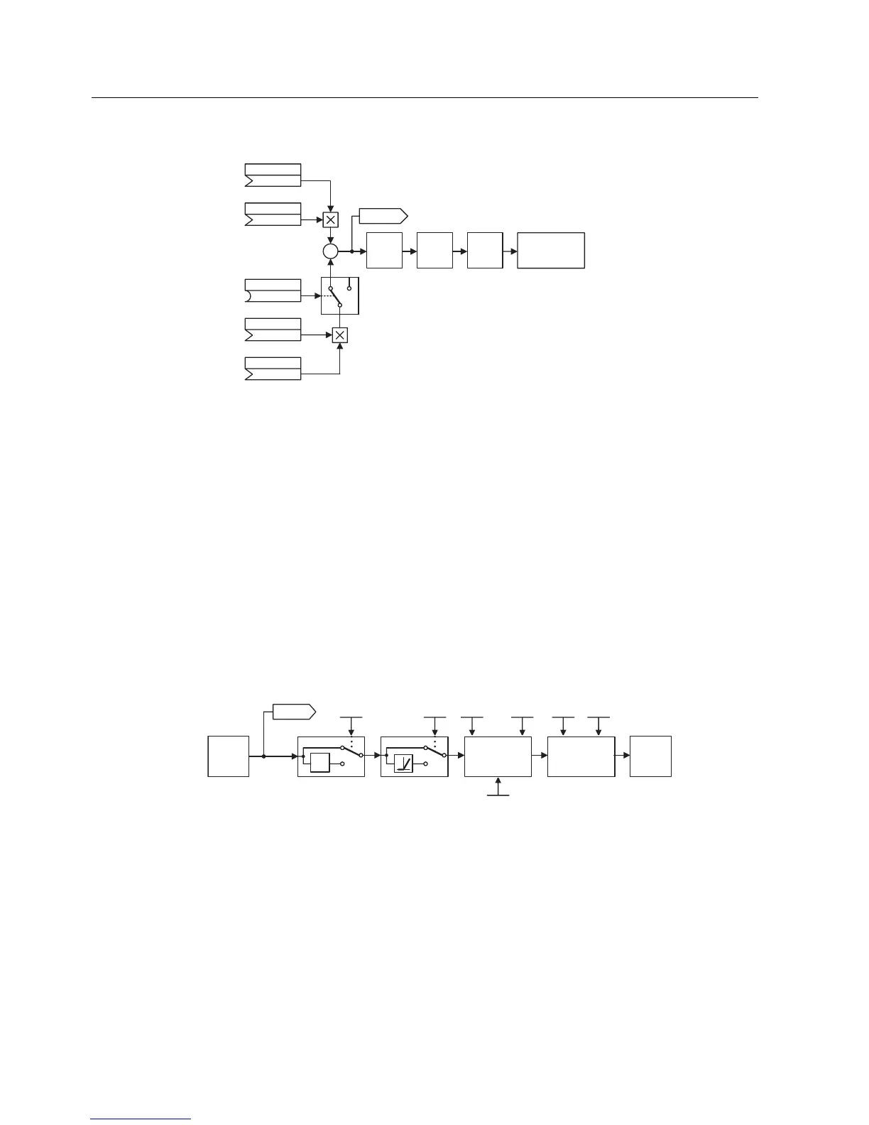
Figure 8-41 Summation
SINAMICS G120 has the following possibilities to select the setpoint source:
1. P1000 – selecting the frequency setpoint source
2. BICO parameterization
– P1070 CI: Main setpoint
– P1075 CI: Additional setpoint
Further, the main setpoint as well as the supplementary (additional) setpoint can be scaled
independently of one another. In this case, for example, a user can simply implement an
override function using the appropriate parameterization.
A scan sequence is generally associated with a forwards and a backwards motion. When
selecting the reversing functionality, after reaching the end position, a direction of rotation
reversal can be initiated in the setpoint channel (see figure below).
On the other hand, if a direction of rotation reversal or a negative frequency setpoint is to be
prevented from being entered using the setpoint channel, then this can be inhibited using
BICO parameter P1110.
3
U
3 3 3
3
3 3
5)*
/LPLW
6NLS
680
Figure 8-42 Modifying the frequency setpoint
Motors can have one or several resonance points in the range from 0 Hz up to the reference
frequency. These resonance points result in oscillations which, under worst case conditions,
can damage the motor load. Using skip frequencies, SINAMICS G120 allows these resonant
frequencies to be passed through as quickly as possible. This means that the skip
frequencies increase the availability of the motor load over the long term.
 Loading...


