Functions
8.15 Brake functions
Control Units CU240S
8-76 Operating Instructions, 11/2006, A5E00766042B AA
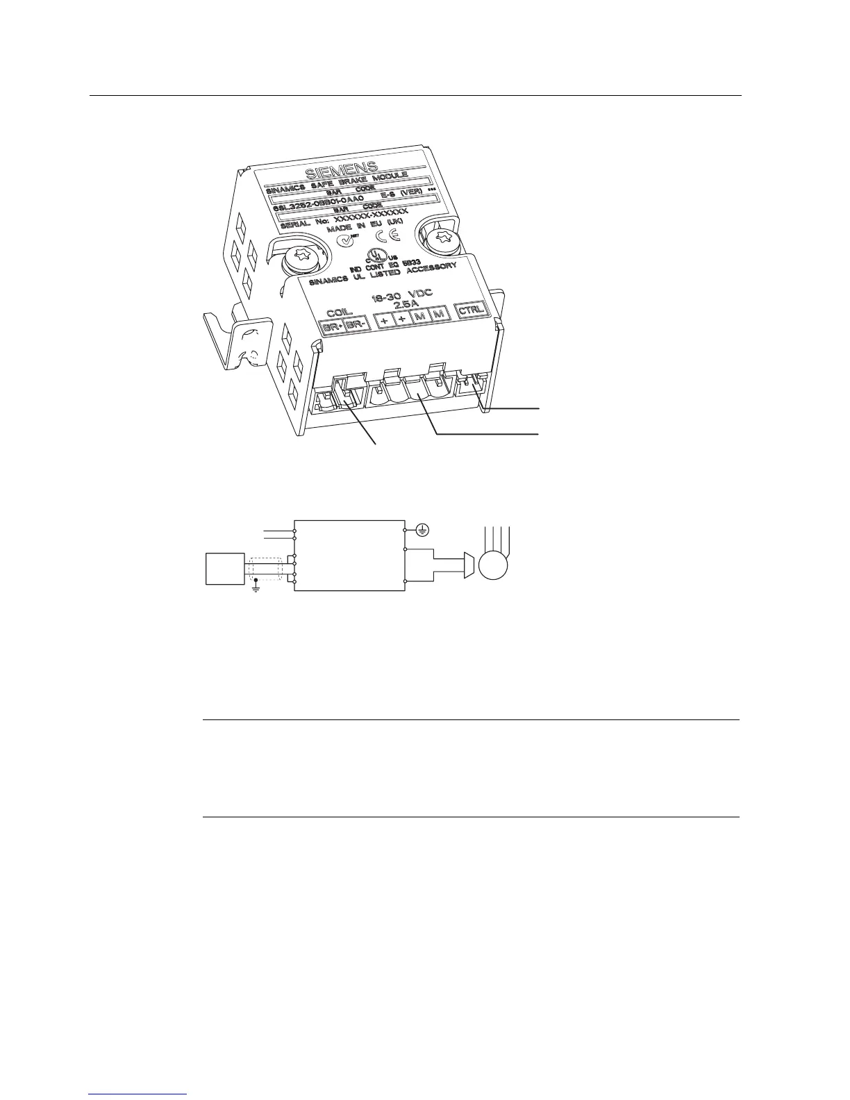
&RQQHFWLRQWREUDNHFRLO
LQVLGHWKHPRWRU
&RQQHFWLRQWR
H[WHUQDO9VXSSO\
)O\LQJOHDGWR3RZHU0RGXOH
Figure 8-52 Safe Brake Module
M
3~
PE
Safe
Brake
Module
&75/
%5
%5
0
0
To
Power
Module (A/B)
to
Power Module
H[W'&
9
Figure 8-53 Wiring of Safe Brake Module
With the Safe Brake Module 24 V motor brakes up to a current consumption of 2 A can be
operated. Necessary is an external controlled power supply for 2.5 A and an output voltage
which can be adjusted at a voltage of 26 V, e.g. SITOP modular. The higher voltage is
required to compensate the voltage drop across the cables to the coil of the brake.
Note
On fail-safe reasons it is not allowed to take the 24 V supply of the Control Unit.
The power supply for the Safe Brake Module must be a separate additional power supply.
During power ON for the drive it is necessary to supply the Safe Brake Module first, so that
the Control Unit is able to check its function, otherwise the fault F1601 will occur.
The Safe Brake Module is designed to reaction to a stepped voltage input, which allows the
braking mechanism to be tested. The Brake Module does not have this functionality.
 Loading...


