Functions
8.15 Brake functions
Control Units CU240S
Operating Instructions, 11/2006, A5E00766042B AA
8-87
_I_ _I_
IBVHW IBVHW
IBDFW IBDFW
WW
W
WW
W
LL
9
'&OLQN
9
'&OLQN
9
'&&RPS
3 9
'&&RPS
෬෭෬3
3ำ9
'&&RPS
෬U
3
:LWKRXW&RPSRXQGEUDNLQJ
3!
:LWK&RPSRXQGEUDNLQJ
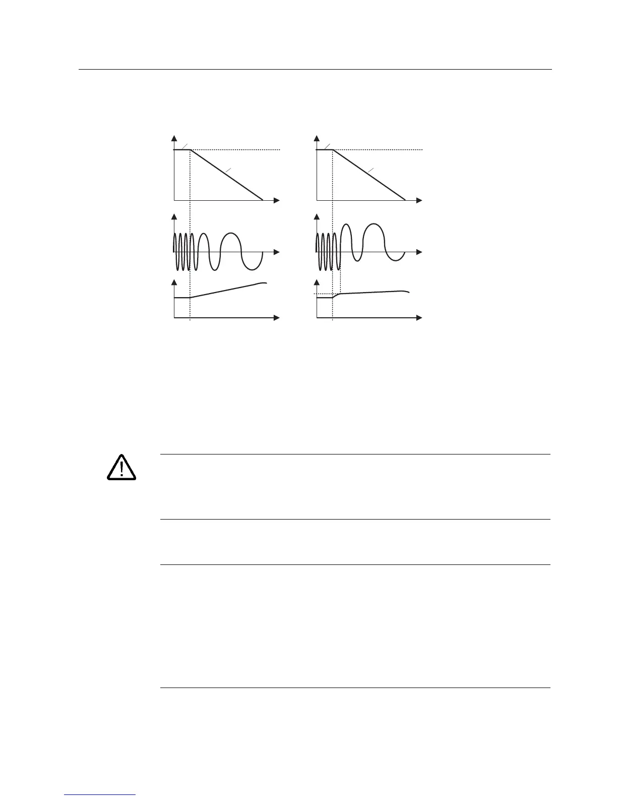
Figure 8-59 Compound braking
The compound braking switch-in threshold VDC-Comp is calculated as a function of
parameter P1254 (Auto detect VDC switch-on levels) either directly using the line supply
voltage P0210 or indirectly using the DC link voltage and r1242 (refer to the formula in the
figure above).
Warning
For compound braking, regenerative braking is superimposed on the DC braking (braking
along a ramp). This means that components of the kinetic energy of the motor and motor
load are converted into thermal energy in the motor. If this power loss is too high or if the
braking operation takes too long, then this can cause the motor to overheat!
Note
Only active in conjunction with V/f control.
Compound braking is deactivated, if:
• flying restart is active,
• DC braking is active, and
• Vector control is selected.
The compound switch-in threshold VDC-Comp is dependent on P1254:
V
DC-Comp
(P1254 = 0) ≠ V
DC-Comp
(P1254 ≠ 0)
 Loading...


