Functions
8.15 Brake functions
Control Units CU240S
8-90 Operating Instructions, 11/2006, A5E00766042B AA
dissipated in the chopper resistor is reduced, which means that the DC link voltage quickly
increases due to the regenerative energy available and the inverter is shutdown (tripped)
due to a DC link overvoltage condition.
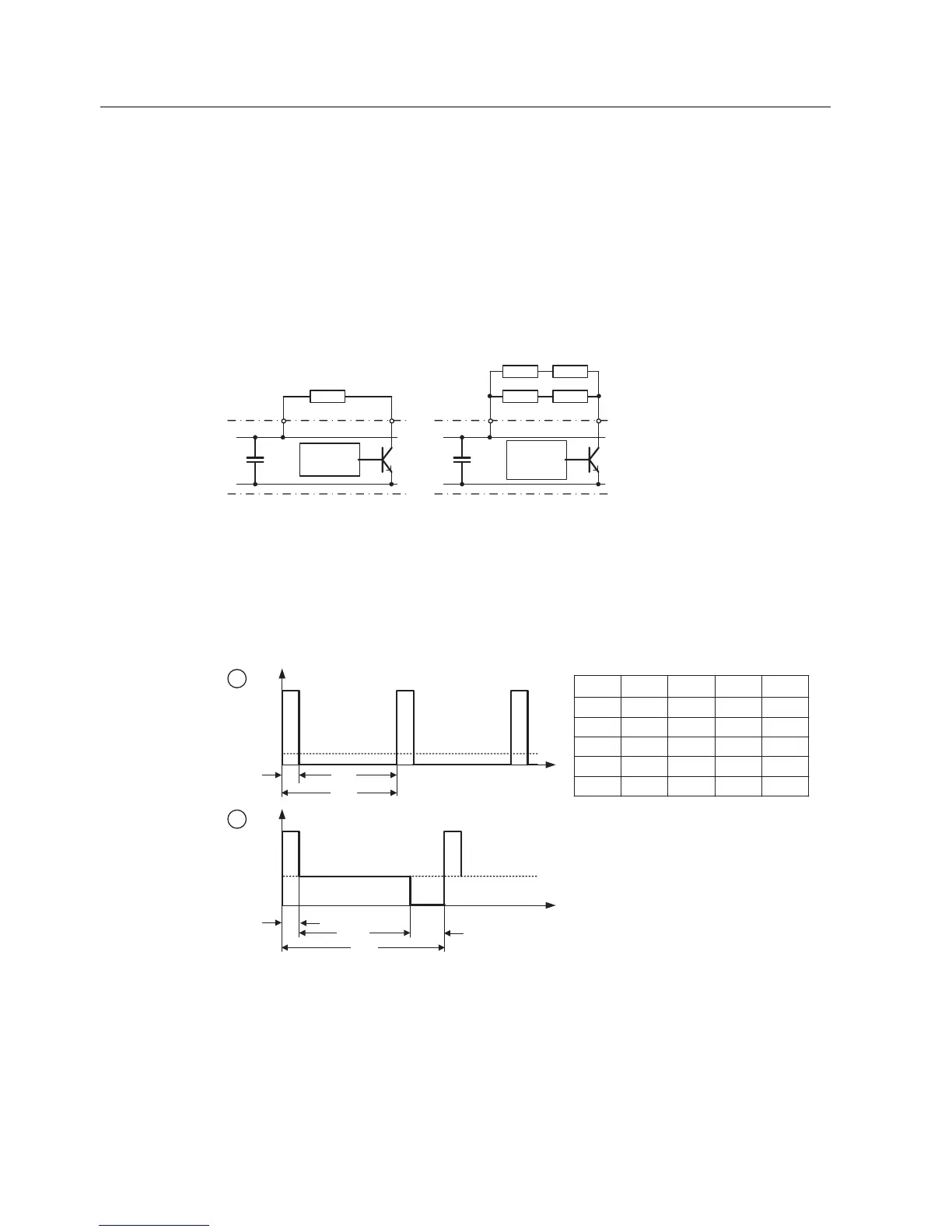
If the continuous power or the load duty cycle for a resistor is too high, then the continuous
rating can be quadrupled using four resistors in a bridge circuit configuration (see figure
below). In this case, in addition, the load duty cycle must be increased using parameter
P1237 from P1237 = 1 (→ 5 %) to P1237 = 3 (→ 20 %). When using the bridge circuit, the
overtemperature switch of the resistors should be connected in series and incorporated in
the fault circuit. This guarantees, that when a resistor overheats, the complete
system/inverter is shut down.
5
55
55
'&35 '&355 5
3
3
&KRSSHU
FRQWURO
&KRSSHU
FRQWURO
Figure 8-63 Increasing the level of braking energy which can be absorbed
The continuous power and the load duty cycle are modified using parameter P1237. If the
load duty cycle monitoring switches from the peak power (100 %) to the continuous power,
then this is dissipated for an unlimited length of time in the braking resistor. Contrary to the
braking resistor, as listed in the Catalog, the chopper control can be permanently operated
with 100 % power.
D
E
W
3
3
3
W
F\FOH
W
W
3
W
F\FOH
W
2))
W
2))
W
2))
W
21
W
21
3
'%
3
'%
3
'%
W
,QILQLWH ,QILQLWH
Figure 8-64 Chopper load duty cycle
For SINAMICS G120, the braking module is integrated in the inverter and the braking
resistor can be connected using the external terminals DCP/R1 and R2 (for more details
refer to Operating Instructions of the corresponding Power Module). Where the DCP/R1 is
the positive terminal for the braking resistor and R2 is the negative terminal for the braking
resistor.
 Loading...


