Functions
8.22 Thermal motor protection and overload responses
Control Units CU240S
Operating Instructions, 11/2006, A5E00766042B AA
8-151
Features
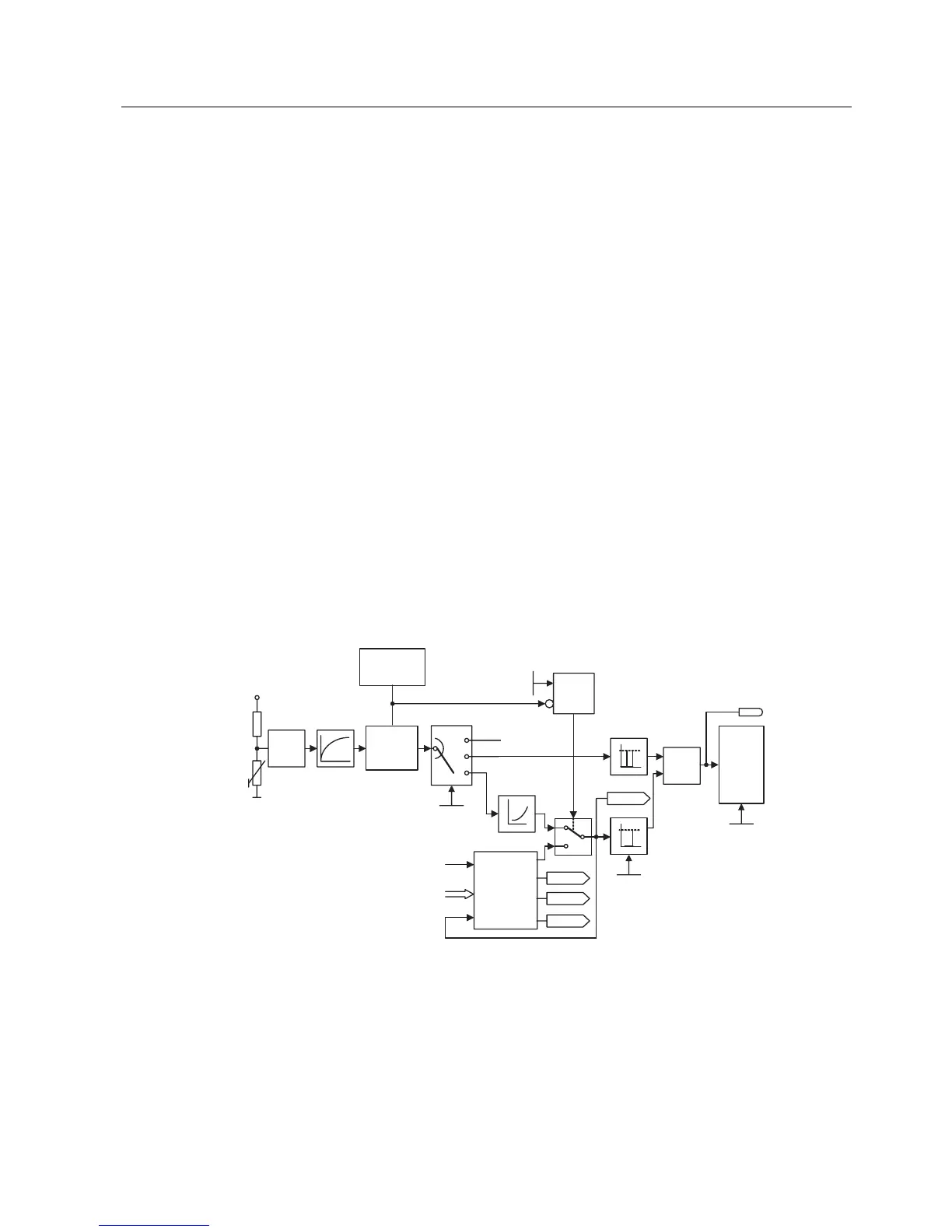
The protective concept (see figure below) distinguishes itself as a result of the following
individual features:
● Protection is effective without using any temperature sensor (P0601 = 0). The
temperatures of various locations in the motor are indirectly determined using a
temperature model.
● It is possible to evaluate temperature sensors. This has the advantage that after a line
supply failure, precise initial temperatures are immediately available. Both PTC sensors
(P0601 = 1) as well as KTY84 sensors (P0601 = 2) can be connected and evaluated.
● When using a KTY84 sensor, the inverter can be parameterized so that a sensor wire
breakage or short-circuit F0015 is detected and the system automatically changes-over to
the temperature model. This means that the inverter is not shut down (tripped) and
operation can continue.
● Selectable temperature warning thresholds P0604 (default: 130 ーC) for operation with the
temperature model or KTY84 sensor. The inverter is shut down or the current reduced
depending on P0610 for a value of P0604 +10 %.
● Selectable responses P0610 which are to be initiated when the warning threshold is
exceeded in order to prevent an overload condition.
● The motor protection has been designed to be completely independent of the inverter
protection. Warning thresholds and responses for inverter protection must be separately
parameterized.
● Various data sets are taken into account in the model. The model is separately calculated
for each data set so that when changing-over between various motors the cooling of the
presently non-active (fed) motors are taken into account.
U
%LW
U
U
U
9
7
V
37&
.7<
3
3
U
ุ
3
3
9
˽
)DXOW
)
$'&
37&
.7<
6LJQDO
ORVV
GHWHFWLRQ
(TXLYDOHQWFLUXLWGDWD
3RZHUGLVVLSDWLRQ3YPRW
7KHUPDO
PRWRU
PRGHO
1RVHQVRU
0RWRU
LW
WHPS
UHDFWLRQ
Figure 8-80 Thermal motor protection
 Loading...


