Installing/Mounting
4.2 Connecting the Control Unit via terminals
Control Units CU240S
4-6 Operating Instructions, 11/2006, A5E00766042B AA
$,
$,
$2
$2
$,
$,
$2
$2
9
,1
9
,1
9 9
37&
37&
'2
1&
'2
12
'2
&20
'2
12
'2
&20
'2
1&
'2
12
'2
&20
(1&
$3
(1&
$1
(1&
%3
(1&
%1
(1&
=3
(1&
=1
',',',',',',',',',
8989
(1&
6833/<
ุN˖
5XQ6WRS
5HYHUVH
$FN
$QDORJ2XWSXW$2
P$P$˖
)DXOW
/DPS2Q
:DUQLQJ
/DPS2Q
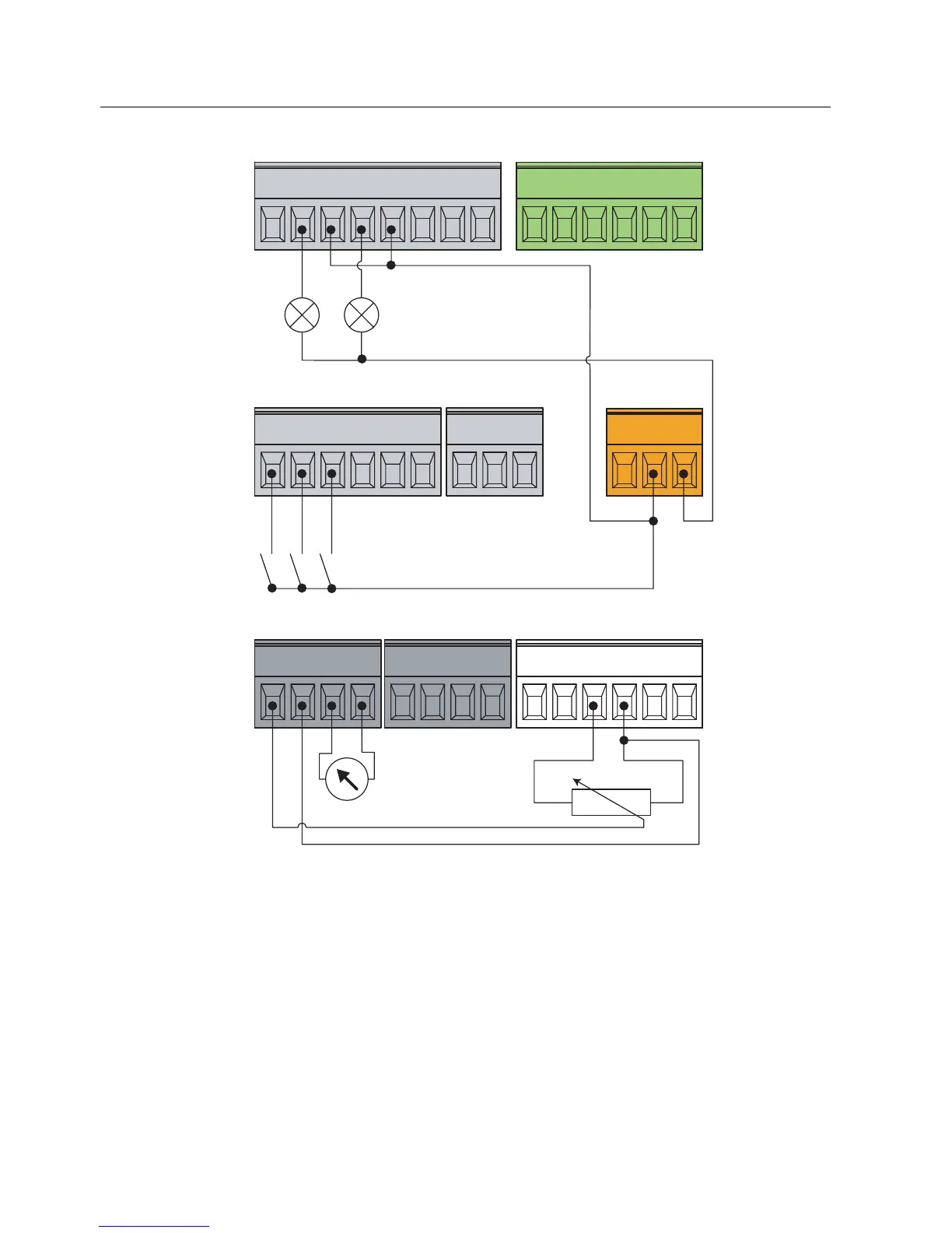
Figure 4-5 Default control wiring of a CU240S
Frequency setpoint and an additional setpoint via terminals
AI0 and AI1 used as voltage inputs
This type of control wiring allows a main frequency setpoint and an additional setpoint to be
established, using potentiometers on analog inputs AI0 and AI1.
The figure below shows the wiring that is necessary to accomplish this functionality.
 Loading...


