Closed-loop thyristor current control
System- and communication configuring D7-SYS - SIMADYN D 5-31
Edition 06.2002
QSF
CAV.dsf
XFO
YAU
[°]
YC
YFO
YFI
KP
KP
(#)
M1
M2
Bit11
Bit10
CX1
IM1
IM2
CX2
AL1
RRC
ARC
NF
XF2
AL2
(
α
INV)
IAV
Fault
eval.
EN >0
ITDC
#
f
f
f
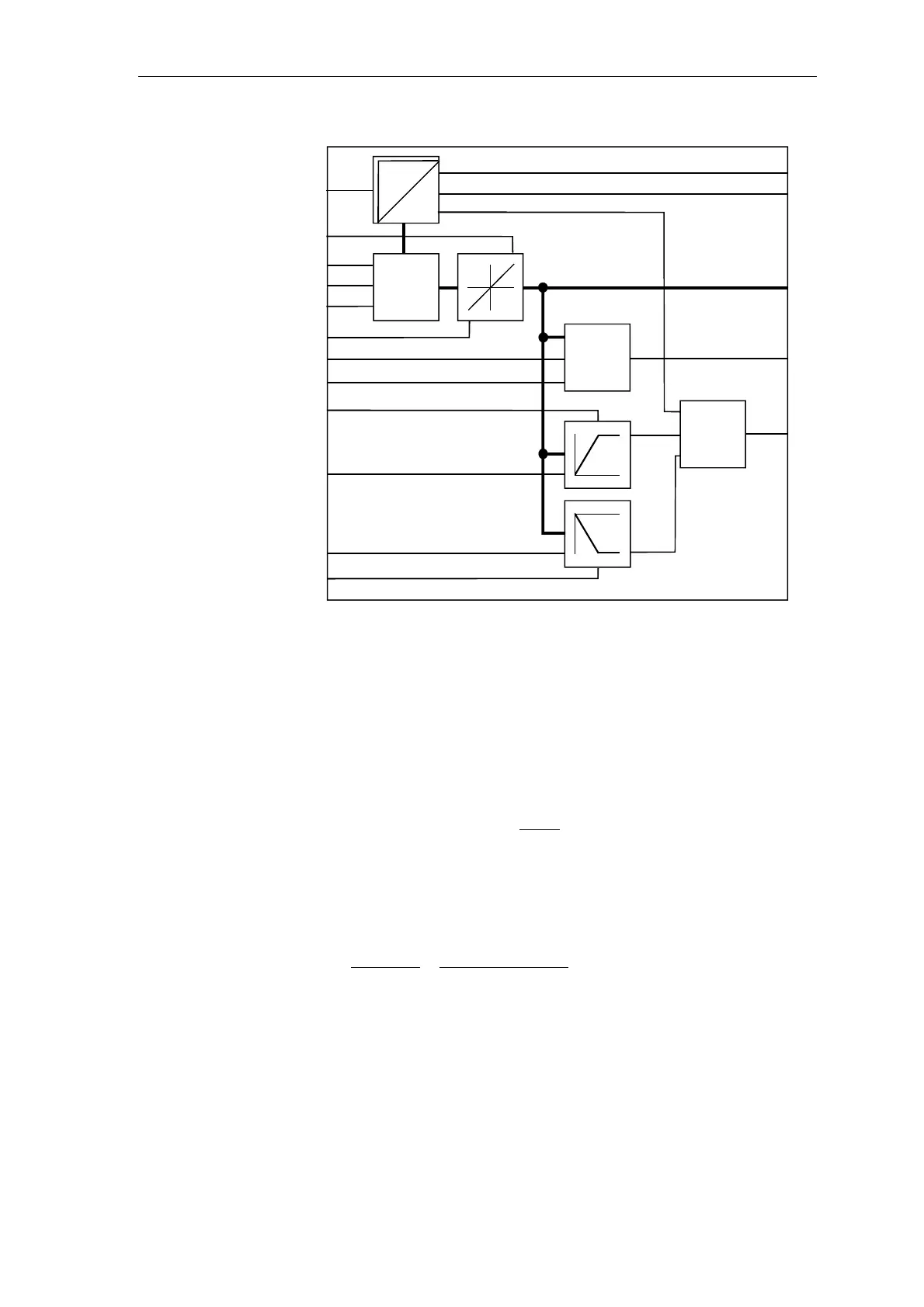
Fig. 5-14 Function chart CAV
The normalized current actual value {0 …1} is displayed at output
CAV.YC with the value CAV.NF = 1.
If NF is set to ARV, the absolute value
=
ˆ
[A] is displayed. If the value is
changed-over, this has an effect on the setting of the controller
parameters!
Calculating the drive converter output current:
with
ARC
Sitor
I
15[kHz]60[kHz]
I
f
⋅+=
rated
I 2 1 0I 1- 2-
[kHz] 09756045 30: range Frequency
∗∗=∗∗
→→←←
The current actual value YC is calculated as follows:
−−
⋅
∗
=
]kHz[15
XFO]kHz[60
I
f
ARC
NFRRC
YC
Output YC is signed.
Calibration frequency of the V/f converter. The center frequency (60[kHz])
of the V/f converter in the Sitor converter has an offset.
The offset frequency for I
A
= 0 [A] is available at connection CAV.YFO.
XFO - 60[kHz] - YFIYFO =
Normalization