Closed-loop thyristor current control
5-32 System- and communication configuring D7-SYS - SIMADYN D
Edition 06.2002
When the closed-loop thyristor current control is switched-out (I=0), the
frequency at YFO corresponds to the offset error of the V/f converter in
the Sitor.
The output only indicates values up to 10% of the system current.
NOTE
Connection CAV.XFO is an initialization connection and is only valid
after a restart \ reset.
CAV.XFO should be determined when commissioning the system and
after the SITOR-converter has been replaced.
Instructions are provided in the Section "Current sensing ".
The inverter stability limit is normally permanently specified at FB PC6
with a value. If the maximum output voltage is to be used, then the limit
must be adjusted as a function of the current, as the overlap angle
increases as a result of the extended commutation. This means that the
inverter stability limit must be reduced in order to avoid “Inverter
commutation faults”. A current-dependent inverter stability limit YAU can
be calculated for these special applications.
0 XF2with ,
2
1arcsin90180 >∗−−°−°=
IAV
XF
ARC
YC
YAU
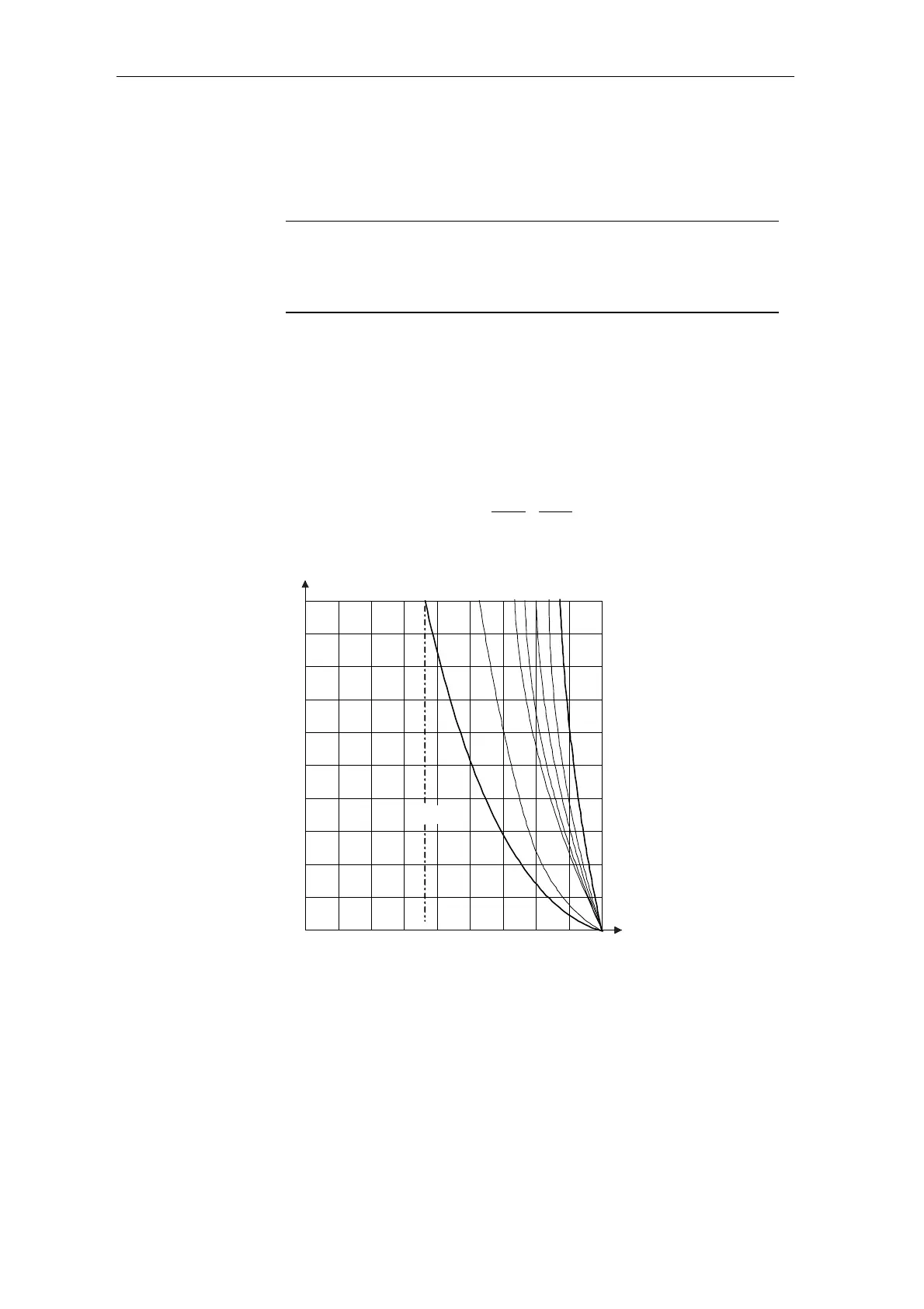
The variations of CAV.XF2 are shown in the diagram.
1.0
1.2
1.4
1.6
1.8
2.0
90°
0.8
0.6
0.4
0.2
0
120° 150° 180°
α
w
20
XF2(%)
10 5 4 3 2 1
α
w max
=
f
(XF2, YC)
|YC| / ARC
XF2 limit
|YC| current actual value
(absolute value)
XF2 inductive voltage drop
of the converter
IAV correction for YUA
α
w
firing angle end pos.:
Inverter
Fig. 5-15 Dynamic inverter stability limit
The data {≥0.7…1.3≤} at connection CAV.IAV results in an additional
correction of the dynamic stability limit.
The bandwidth of the correction of CAV.IAV decreases with CAV.XF2 ⇒
0.
Line supply changes can be taken into account here.
Negative inverter
limit characteristic