25/617
Building Technologies Division User Manual LMS14... CC1U7471en
3 Mounting and installation 28.01.2015
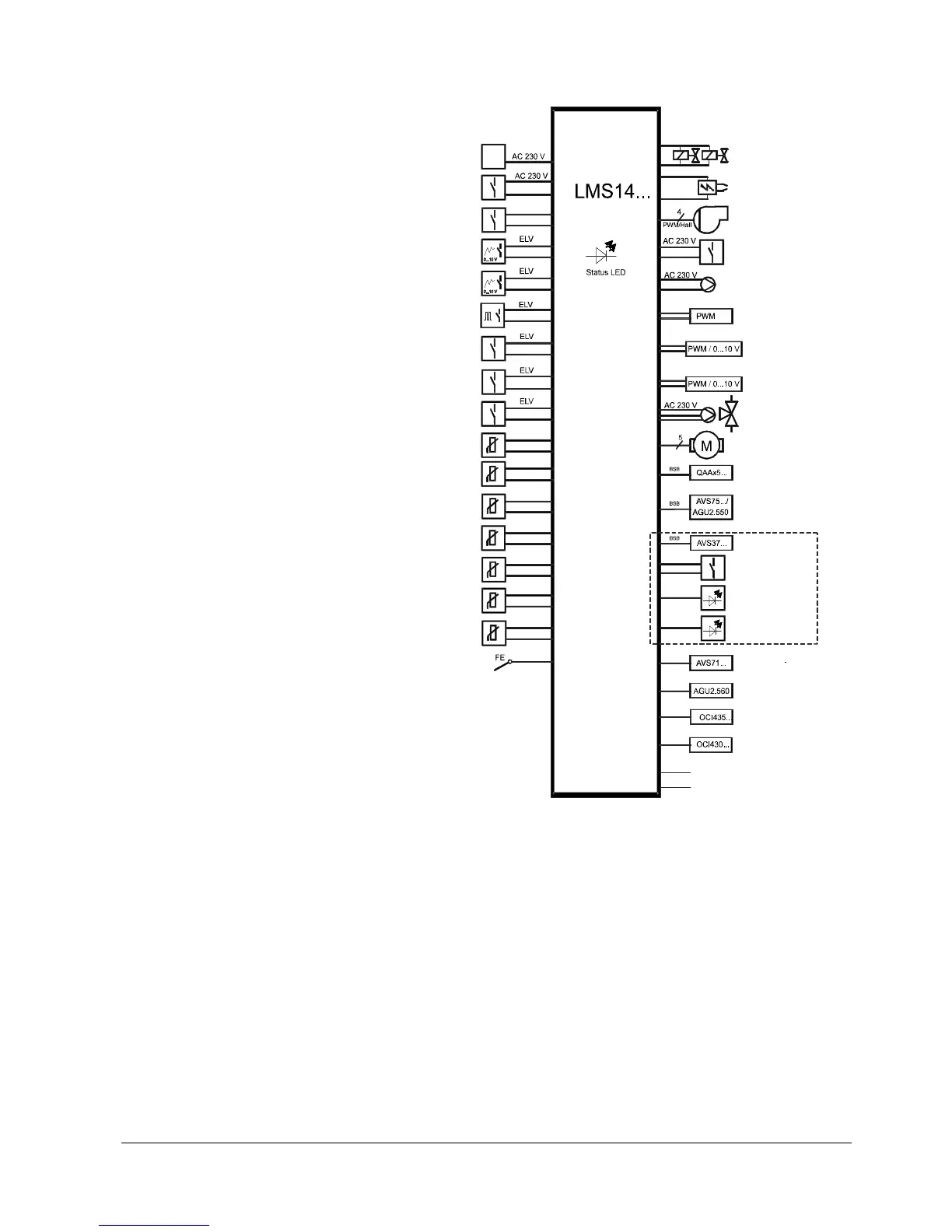
3.3 Basic diagram LMS14…
7471a44e/1214
Mains voltage
Lockout
(Safety temperature limiter,
Temperature limiter)
Lockout reset button
Programmable analog /
digital input
Programmable analog /
digital input
Programmable frequenzy /
digital input
Programmable digital
input
Gas pressure switch or programmable
digital input
Air pressure switch or
program mable digital
input
Boiler flow sensor
DHW sensor 1
Outside sensor
Multifunction sensor
Multifunction sensor
Multifunction sensor
Boiler return sensor /
multifunction sensor
Flame supervision
(continuous)
L1, N, PE / L1, L2, PE
(L1 / N )
replaceable
(S)TB / TB
Reset
H1
H3
H4
H5
H6
H7
B2
B3 / B38
B9
BX1
BX2
Bx3
Return flow B7 / BX4
Threshold programmable /
Dual or single electrode operation
Fuel valve
AC 230 V
Ignition module
AC 230 V
Variable Geschwindigkeit
PWM fan
AC 230 V
Multifunction
outpur
Heating circuit pump
Analog output
Analog output
Analog output
DHW pump 1
or diverting valve
Unipolar / bipolar
stepper motor
(diverting valve)
Room unit S / 1 / 2 / 3
Extension module 1 / 2 / 3
Operator unit
Reset
LED interference
LED flame
Radio module
Parameter stick
LPB module
PC tool
Line AUX1 (fuse)
Line AUX2 (fuse)
QX1
QX2
P1
UX2
UX3
QX3
QX4
Figure 3: Basic diagram
The diagram shows the full scope of functions of the LMS14… system.
The actual functions are to be determined based on the respective
execution/configuration.