417/617
Building Technologies Division User Manual LMS14… CC1U7471en
6 The settings in detail 28.01.2015
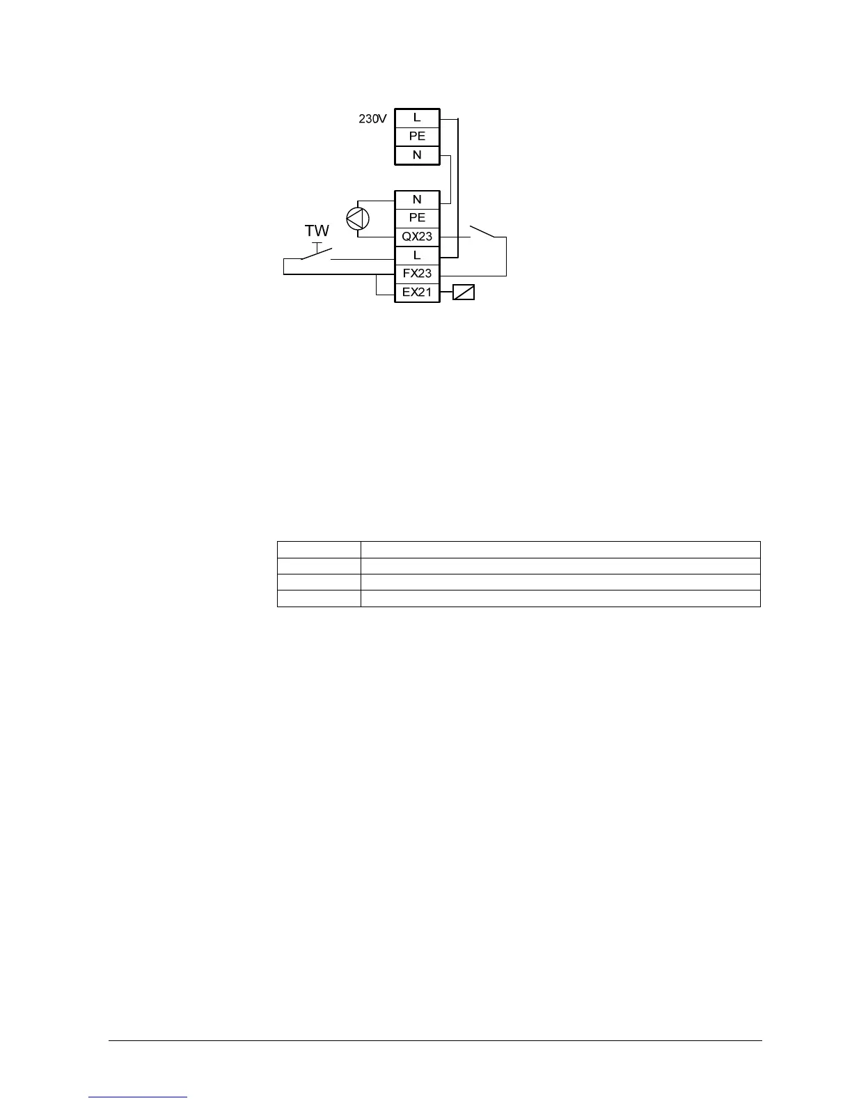
Wiring example:
Figure 91: Extensions module – limit thermostat HC
Key
TW Limit thermostat
The state of 0 V is always interpreted as Limit thermostat cut out.
The state at input EX21 is transmitted to the basic unit where it is evaluated for the
generation of error messages. The input test also shows the state (0 V/230 V).
Since inside the module input EX21 acts on the states of the relays, the limit thermostat
continues to be active even if communication with the basic unit is interrupted.
If the Limit thermostat function is not desired, the parameter settings for input EX21
must be appropriately changed.
Line no. Operating line
7950 Input EX21 module 1
7951 Input EX21 module 2
7952 Input EX21 module 3
Signal state: 0 V/230 V
The current operating state can be verified on operating page Status.
Info/diagnostics
Operating state

 Loading...