Configuration
5.2 Configuring workflow
1FN3 linear motors
108 Configuration Manual, 10/2018, 6SN1197-0AB86-0BP2
Both components depend on the type of linear guide used and its loading. Loads are also
included which, depending on the mechanical design version, especially include the forces
due to gravity (F
⊥
from the diagram above) and magnetic forces of attraction F
magn
between
the motor components as well as tension forces F
spann
between the various guide elements.
All these forces result in a force F
n
that is perpendicular ("normal") to the axis:
F
n
= F
⊥
+ F
magn
+ F
spann
If you set F
rc
= μ
rc
‧ F
n
and F
rv
= μ
rv
‧ v ‧ F
n
, the frictional force will be
F
r
= μ
rc
‧ F
n
+ μ
rv
‧ v ‧ F
n
High linear motor velocities can also result in extremely high frictional force values. Note the
specifications of the linear guide manufacturer for the calculation of the frictional forces!
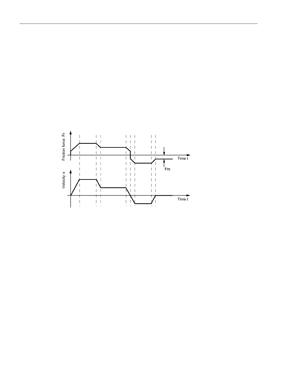
The following figure shows a simplified example for the velocity curve and the
correspondingly occurring frictional forces in a motor.
Figure 5-3 Example of frictional forces

 Loading...


