Electrical connection
8.3 System integration
1FN3 linear motors
498 Configuration Manual, 10/2018, 6SN1197-0AB86-0BP2
Power connection
Connection assignment
Table 8- 3 Power connection for linear motor
V2 V
For information on connecting the power, also refer to the diagrams relating to "System
integration". The direction of motion of the primary or secondary section is positive if the
primary section is connected to phase sequence U, V, W. See "Direction of motion of the
motor (Page 35)".
Number of conductors and cable cross-sections
Cables that are connected to the motor must have four conductors for the power cable / four
conductors for the signal cable. The cross-section for each of the signal cable conductors is
0.5 mm
2
. The cross-section of the power cable conductors is based on the rated current of
the motor. The rated current of the motor must be less than the current carrying capacity of
the cable according to DIN EN 60204-1 (laying system C). The table below specifies the
maximum permissible rated current of the motor for different cross-sections of the power
cable conductors.
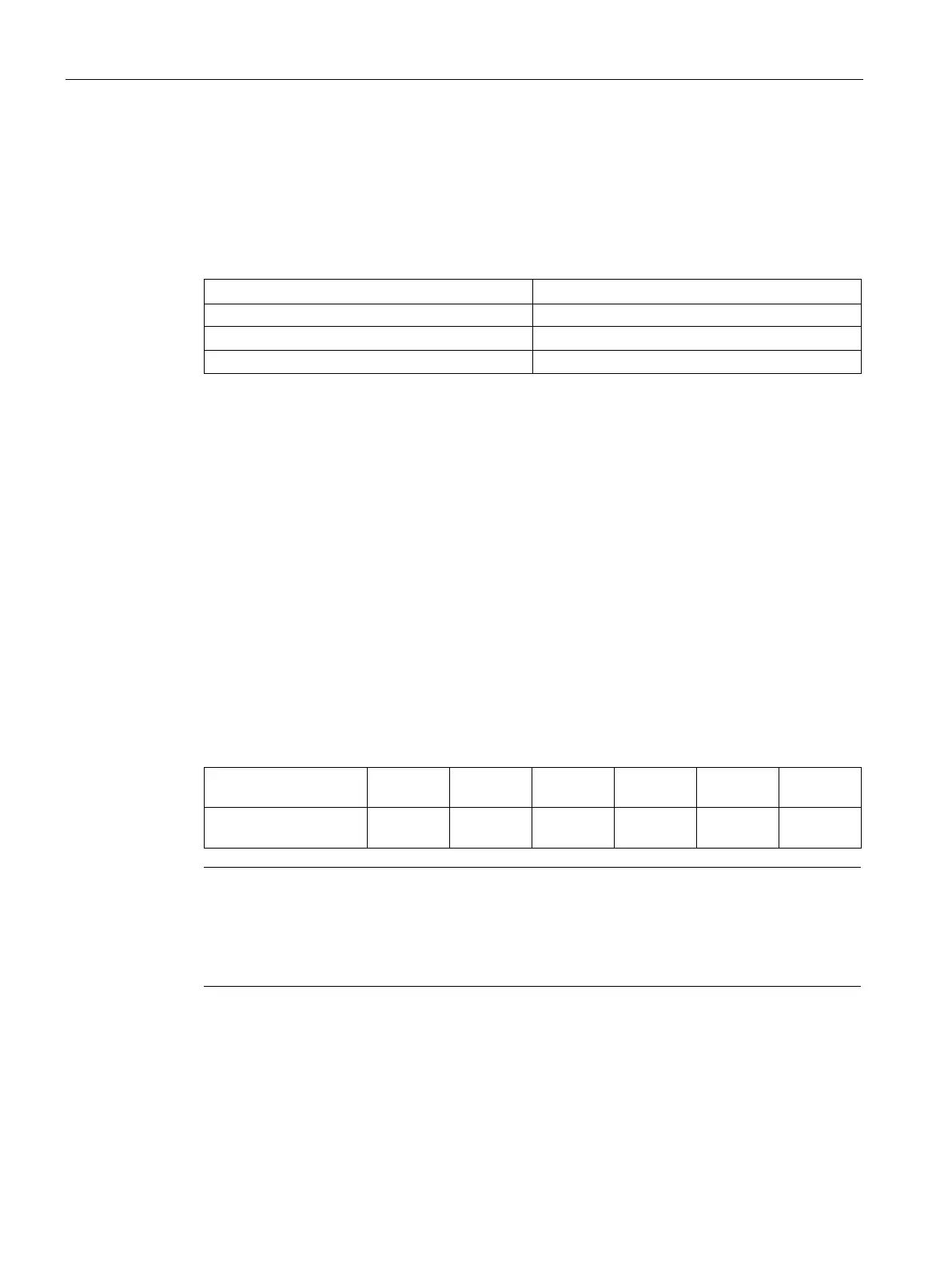
Table 8- 4 Maximum permissible rated current with different cross-sections of the power cable
conductors
Power cable conductor
cross-section
2.5 mm
2
4 mm
2
6 mm
2
10 mm
2
16 mm
2
25 mm
2
Maximum permissible
rated current
21 A 28 A 36 A 50 A 66 A 84 A
Note
Connection of large cable cross-sections
Connecting cables with conductor cross
-sections of more than 16 mm
2
is not possible at the
motor terminal panel. If the rated current of a motor requires power conductors with a cross
-
mm
2
, please contact your local Siemens office.

 Loading...


