Configuration
5.3 Examples
1FN3 linear motors
130 Configuration Manual, 10/2018, 6SN1197-0AB86-0BP2
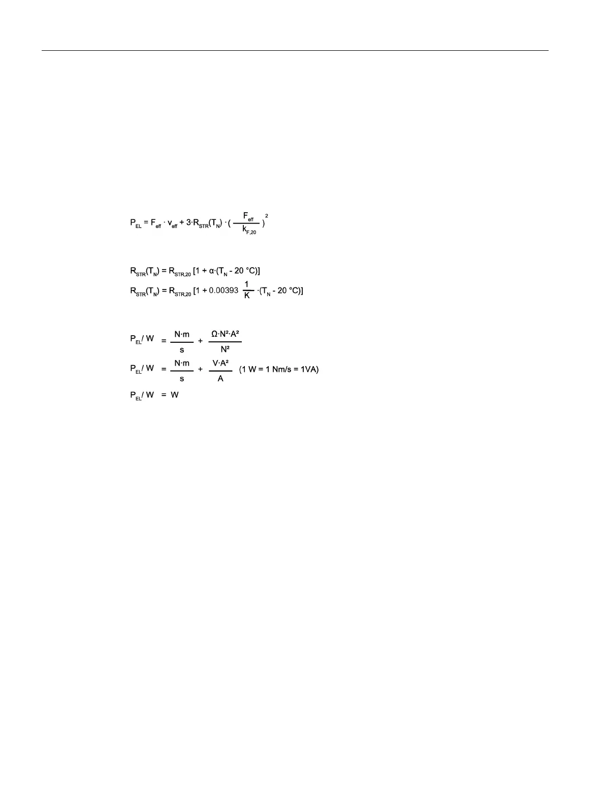
Calculating the infeed power
The electrical infeed power is obtained from the mechanical power P
MECH
and the power loss
of the motor P
V,Mot
. The rms values of the motor velocity and motor force resulting from the
duty cycle are used as basis for the calculation.
The rms infeed power is estimated as follows:
P
EL
= P
MECH
+ P
V,Mot
with
Controlling the unit:
To dimension the infeed (Active Infeed), in addition to the calculated value P
EL
, the power
loss of the Motor Module P
v,MoMo
and the Active Infeed P
V,AI
must also be added (see
Chapter "Calculation of the required infeed (Page 120)").
Gantry with transverse axis
Machining center with gantry axis
Frequently, an axis design in the form of a gantry is used for machining centers. The center
area of the slide of the gantry axis is required as machining space. This means that the
gantry is moved using two identical linear motors arranged at the sides.
The two motors are controlled from their own separate drive system – equipped with their
own position measuring system (gantry arrangement).
In the simplest scenario, the gantry has a symmetrical design, which means that each motor
must accelerate half the mass m
P
of the gantry.
In addition, an additional axis (transverse axis moving with the gantry) can be additionally
attached to the gantry, whose slides can be moved out of the center position. Depending on
the particular operating case, the mass distribution is no longer symmetrical. In this case, the
two motors of the gantry have to move different masses.

 Loading...


