Configuration
5.3 Examples
1FN3 linear motors
Configuration Manual, 10/2018, 6SN1197-0AB86-0BP2
131
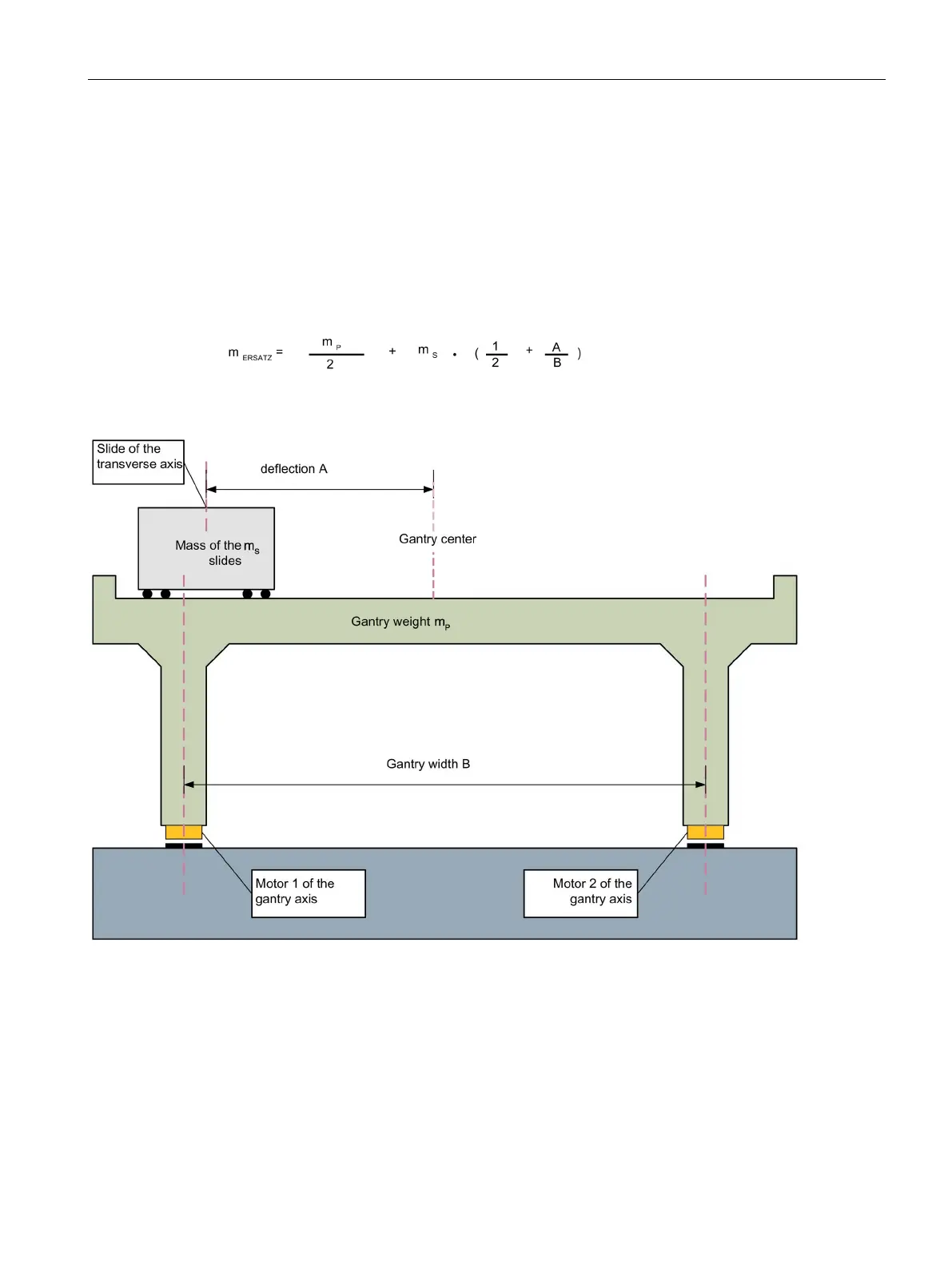
Depending on how far this transverse axis is moved out of the center position, the slide mass
m
S
is distributed between both motors of the gantry axis. This means that in addition to half
the mass of the gantry, the individual motor also has to move the percentage mass of the
transverse axis slide.
It is sufficient to use the most unfavorable scenario when dimensioning the two motors.
In this case, the slide of the transverse axis is fully moved to one side. For reasons of
simplicity, the maximum possible movement at both sides is assumed to be identical.
The equivalent mass m
ERSATZ
is calculated from the gantry mass m
P
and the slide mass m
S
:
Figure 5-16 Example of a machining center with gantry axis
The drive is now dimensioned based on the equivalent mass - and is only carried out for one
motor. The result is also valid for the other motor.

 Loading...


