Configuration
5.4 Mounting
1FN3 linear motors
142 Configuration Manual, 10/2018, 6SN1197-0AB86-0BP2
Screw-in depths for the secondary section installation
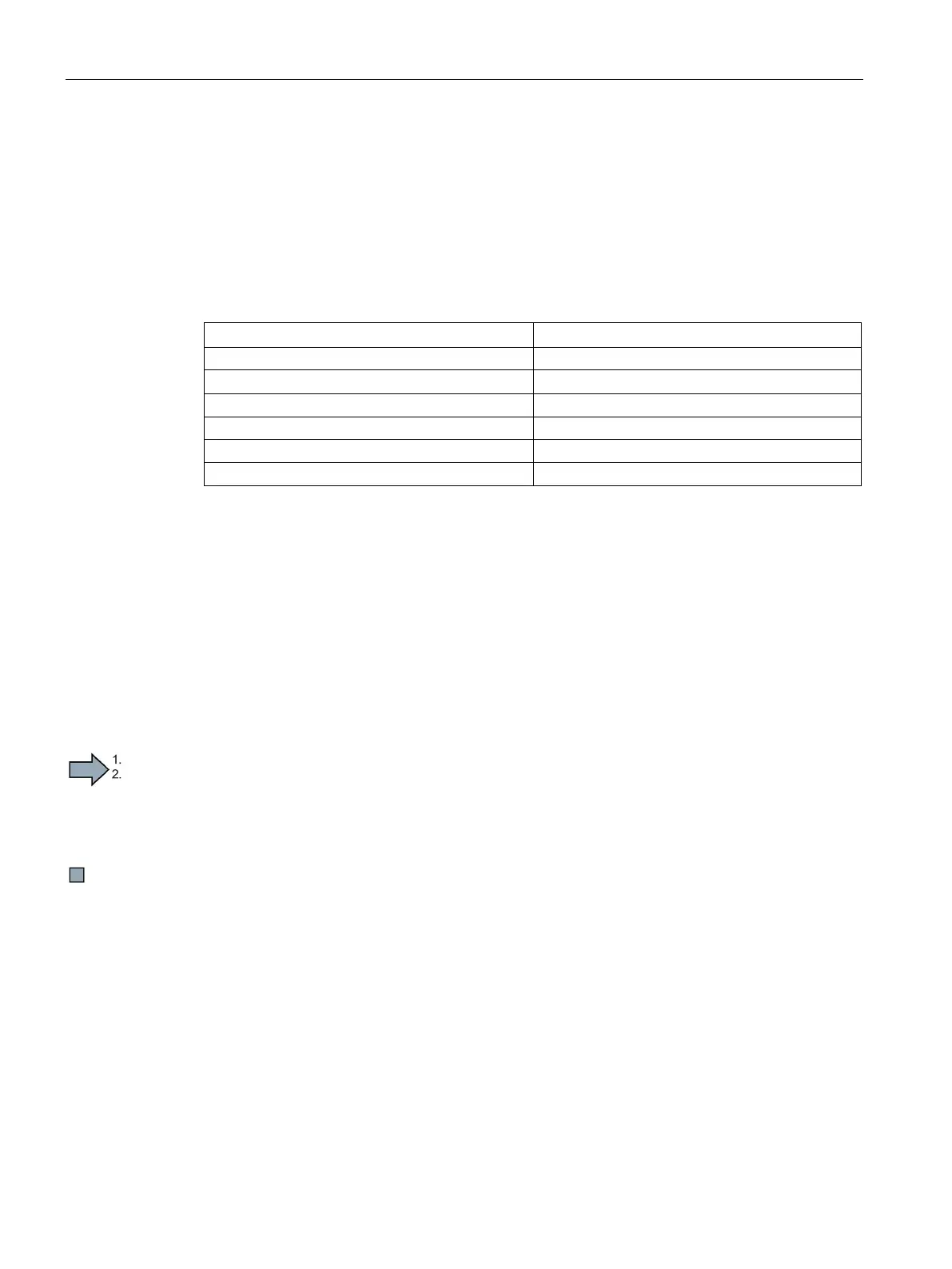
Minimum permissible screw-in depth
The minimum permissible screw-in depths for the most commonly used materials for a
machine bed are listed below. For different materials, you must determine the screw-in depth
according to VDI Directive 2230.
Table 5- 2 Minimum permissible screw-in depths
EN GJL-300 1.3 • d
The maximum screw-in depth is at the discretion of the machine manufacturer.
The maximum screw-in depth is specified by the threaded holes in the customers machine
bed.
Procedure when installing the motor
Installing a linear motor is subdivided into the following steps:
1. Check the installation dimension before installing motors
2. Clean the mounting surfaces for motor parts and the machine.
3. Installing primary sections, secondary sections and components
4. Checking the motor installation

 Loading...


