Configuration
5.4 Mounting
1FN3 linear motors
Configuration Manual, 10/2018, 6SN1197-0AB86-0BP2
141
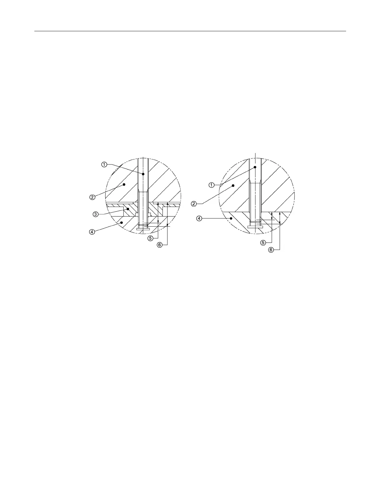
Thread depth and screw-in depths in the primary section
The following drawings schematically illustrate the minimum permissible and maximum
screw-in depth of the mounting screws in the screwed-in state, with and without the use of a
precision cooler. For selecting the screw length, a
is thus made available to the
machine manufacturer.
The selection of the length of the mounting screws while taking all of the design tolerances
into consideration is the responsibility of the machine manufacturer.
The machine manufacturer must ensure that the minimum screw-in depth is reached and the
maximum screw-in depth is not exceeded.
Figure on the left: Primary section with precision cooler, figure on the right: Primary section without
-
The minimum screw-in depth and maximum screw-in depth as shown in the installation
drawing of the primary section in the Configuration Manual under ① "Screw-in depth MP"
Figure 5-19 Schematic diagram for the screw-in depths in the primary section

 Loading...


