Assembly drawings/dimension sheets
9.3 1FN3050, 1FN3100, 1FN3150
1FN3 linear motors
Configuration Manual, 10/2018, 6SN1197-0AB86-0BP2
527
Dimensions of the secondary section end pieces of 1FN3150
1FN3150-0TF00
1FN3150-0TG00
1FN3150-0TJ00
Hole distance to secondary section hole
G 1/8 cooler connector position (height)
Hole pattern (transverse)
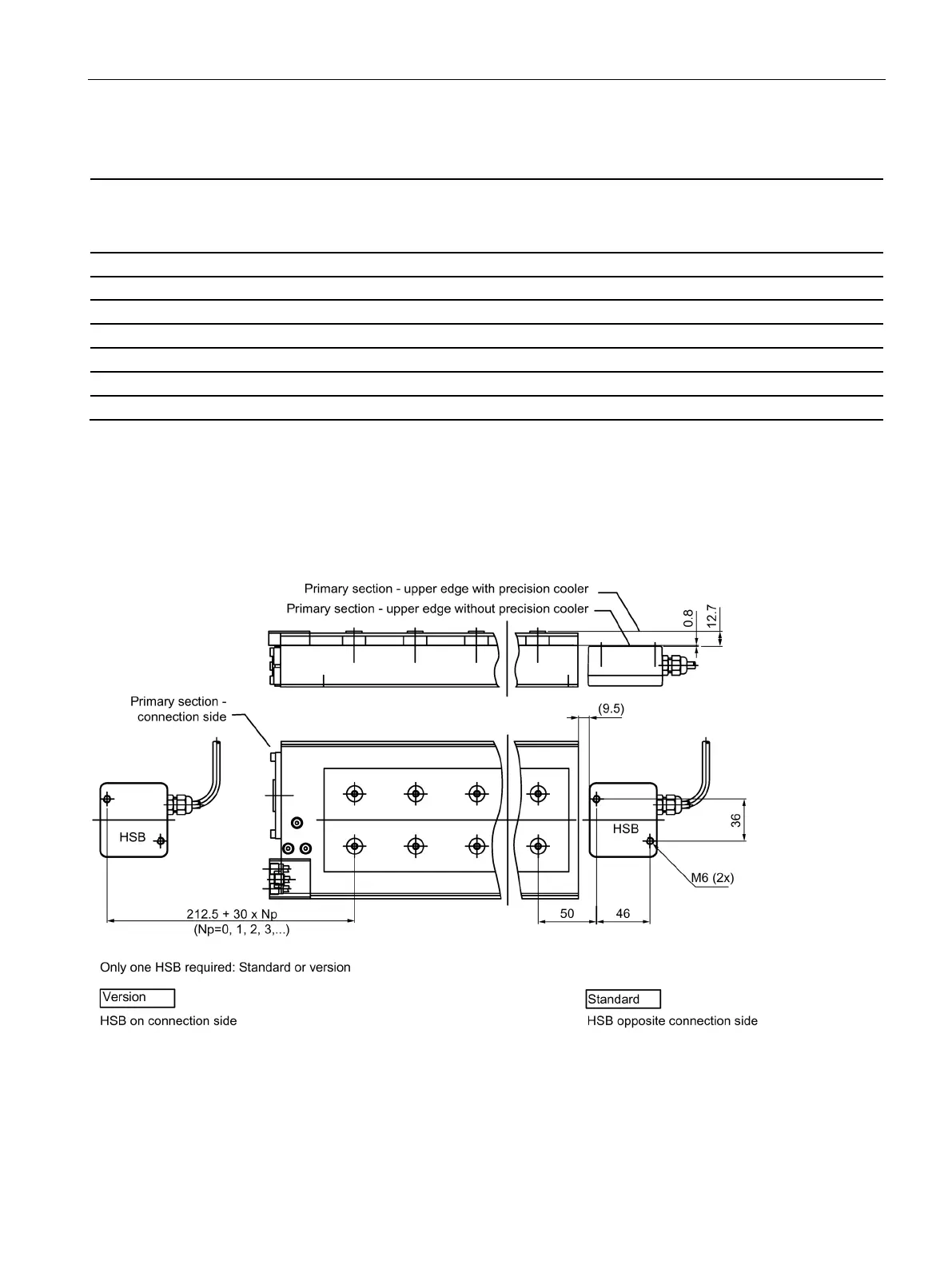
Mounting the Hall sensor box
Mounting the Hall sensor box onto the peak load motors 1FN3050 - 1FN3150
Figure 9-8 Hall sensor box (HSB) with straight cable outlet for motors 1FN3050, 1FN3100 and 1FN3150

 Loading...


